00198574-01_Process_Foundation_DEK_Micron_EN - 第32页
5 Product File and Machine Setup 5.3 Setup Synthetic Fiducials 32 Process Foundation DEK Micron-Series 12/2017 Fiducial Positions Exercise Create a new product file from the default five giving it a name and product ID. …
5 Product File and Machine Setup
5.2 Create a New Product File
Process Foundation DEK Micron-Series 12/2017 31
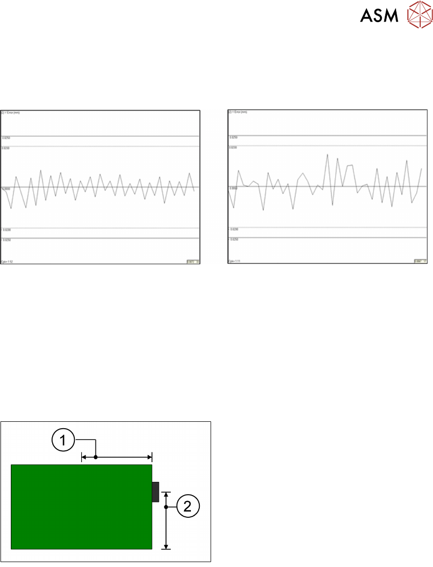
Importance of Accurate Board Width
The DEK printer has an automatic allowance of 0.2mm extra in the width to compensate for board
variations. Adding to this will decrease the effectiveness of the edge clamps and may lead to
misalignment of the printed image. An example demonstrating the effect of increasing the rail width
by just 0.5mm has on Y-axis alignment repeatability can be seen below.
Rail width parameter set to 250mm Rail width parameter set to 250.5mm
SPC graphs showing Post print "Y" alignment repeatability on a DEK06 test board.
Keep rail width as tight as practically possible!
Board Stop Position
The board stop is a mechanical bracket that is mounted on the camera assembly. It is driven
down between the rails as the board travels along the transport belts and stops the board in the
area of the stencil image.
Its default position is X = 0.5 x board length*, Y = 0.66 x board width*. These coordinates can be
adjusted in the edit page. Note, however, that if any board dimension is later adjusted, the board
stop will automatically revert back to the default position!
1. Board Stop X
2. Board Stop Y
The board stop position could be adjusted, for instance to avoid cut out sections or to place the
stop closer to the rails to stop large or warped boards from slipping underneath.
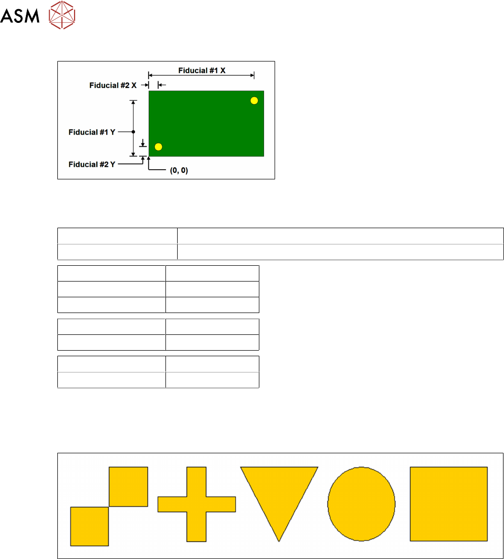
Which Fiducial First?
Unless you are using the remote board stop option, the cycle time of the printer can be optimised
by making sure the first fiducial is the rightmost fiducial. This is because the camera holds the
standard board stop, which will always be on the right edge of the PCB. So putting the first fiducial
closer to the right will reduce the time it takes to travel around the fiducials. The bigger the
substrate: the greater the time saving. The following diagram indicates how to measure the fiducial
positions:
5 Product File and Machine Setup
5.3 Setup Synthetic Fiducials
32 Process Foundation DEK Micron-Series 12/2017
Fiducial Positions
Exercise
Create a new product file from the default five giving it a name and product ID.
Product Name
Product ID
Substrate Width mm
Substrate Length mm
Substrate Thickness mm
Fiducial #1 X mm
Fiducial #1 Y mm
Fiducial #2 X mm
Fiducial #2 Y mm
5.3 Setup Synthetic Fiducials
Standard synthetic fiducial shapes should be used whenever available. These must align to
corresponding fiducials on the underside of the stencil.
Failure to set up the fiducials correctly could result in print offsets or vision error messages.
It is possible to program three pairs of fiducials but this is rarely necessary. It may help if the board
is very large, or has many panels and is showing alignment problems.
Exercise
1. Set up two pairs of synthetic fiducials for your board file
2. If the "Auto Fiducial Set up" option is available, use this option to repeat the setting up of the
fiducials
Notes:
………………………………………………………………………………………………………………
………………………………………………………………………………………………………………
5 Product File and Machine Setup
5.4 Setup Video models
Process Foundation DEK Micron-Series 12/2017 33
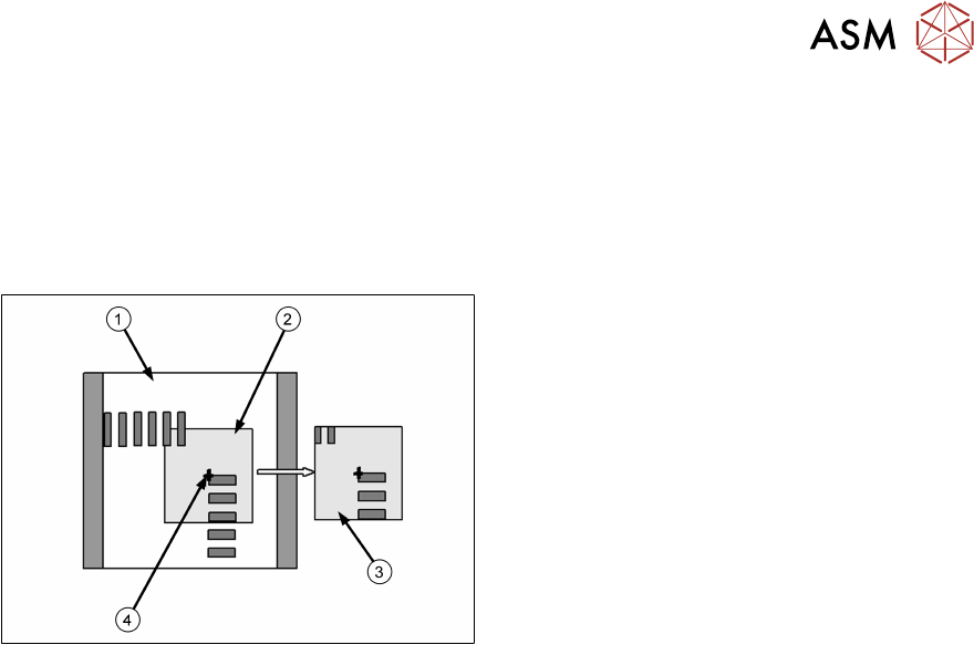
5.4 Setup Video models
The video model option is useful when there are no synthetic fiducials on the board or stencil, or
when the fiducials are very poor quality. The secret of success is to pick an area of the image that
is unique within the field of view, as shown below.
The image below is using the corner of a component and, of course, it will have a corresponding
set of apertures on the stencil to align to.
1. Field of View
2. Sample Window
3. Learned Model
4. Alignment Point
Problems and Limitations
Video models should never be considered as a first choice for alignment as there are several
disadvantages:
●
Due to the normal practice of using aperture reduction, the alignment point of the stencil video
model is unlikely to match that of the board. Therefore, the need to program print offsets is
common when using video models.
●
The stencil capture score may deteriorate rapidly once the stencil is contaminated with paste.
Although this can often be corrected with lighting adjustment, it is sometimes necessary to
use the under-screen cleaner more often than is desirable, sometimes after every print!
●
On a heavily populated board it is often difficult to find an area that contains a unique image.
The software may detect multiple possible targets within the field of view. If this happens it
may help to increase the Accept Score so that only the true video model will be captured.
Exercise
Create a new board file based on the one you created previously, give it the name "Video" and ID
"Video Model Practice". Set up two pairs of video models.