00195376-05_SM_D1_D1i_D2_D2i_EN.pdf - 第100页
Service Work PCB conveyor system 4 .3.9 Replac ing the Lifting Table Fork Light Barrier [00363 111] 100 Service Manual SIPLACE D1/D1i/D2/D2i Installation 4.3.9 4 . 3 . 9 R e p la c in g t h e L if t in g T a b le F o r k…
Service Work
4.3.8 Replacing the Complete Lifting Table Cylinder [00358703] PCB conveyor system
Service Manual SIPLACE D1/D1i/D2/D2i 99
► Loosen the screws fastening the lifting table plate and remove the lifting table plate from the lifting
table unit.
► Switch off the compressed air supply and release the air at the pneumatic unit filter.
► Loosen the screws fastening the connection plug and then unplug it.
► Detach the compressed air connections and remove the old solenoid valve.
► Fit the new solenoid valve and reconnect the electrical and compressed air systems.
► Check the speed of the lifting table cylinder and correct where necessary (see "6.7.11.2 Adjusting
the Lifting Table Speed" [ ➙ 273]).
4.3.8
4.3.8 Replacing the Complete Lifting Table Cylinder [00358703]
Replacing the Complete Lifting Table Cylinder [00358703]
Overview
Removal
DANGER!
Press the EMERGENCY STOP!
Before performing adjustment work you must ensure that
the lifting table has been secured against movement.
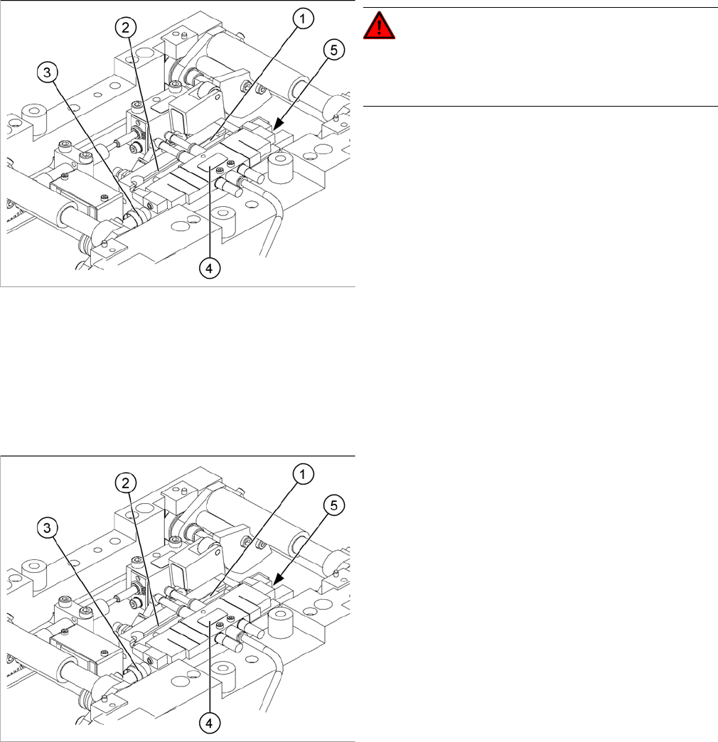
Legend
1. End position proximity switch
2. Lifting table cylinder
3. Piston rod with locknut
4. Solenoid valve
5. 2x fastening screws for lifting table cylinder (at side)
► Move the PCB conveyor to the position which gives
you best access to the lifting table.
► Move the Y gantries into the area outside the PCB
conveyor.
► Switch off the machine and secure it to prevent unau-
thorized reactivation.
► Switch off the compressed air supply.
► Loosen the screws fastening the lifting table plate and
remove the lifting table plate from the lifting table unit.
► Loosen the fastening screws for the solenoid valve
(4) and remove it from the lifting table cylinder. You
may need to unplug the cables and hoses from the
solenoid valve and loosen the relevant cable ties.
► Loosen the grub screw at the end position proximity
switch (1) and push the end position proximity switch
out of the lifting table cylinder guide rail (2). Open the
corresponding cable ties to help you.
► Loosen the locknut on the piston rod (3) and twist the
piston rod out until it releases itself from the actuator.
► Loosen and remove the two screws fastening the lift-
ing table cylinder (2).
Service Work
PCB conveyor system 4.3.9 Replacing the Lifting Table Fork Light Barrier [00363111]
100 Service Manual SIPLACE D1/D1i/D2/D2i
Installation
4.3.9
4.3.9 Replacing the Lifting Table Fork Light Barrier [00363111]
Replacing the Lifting Table Fork Light Barrier [00363111]
Parts
▪ Light barrier for track A (up) – single conveyor [00363111-xx]
▪ Light barrier for track B (down) – single conveyor [00363113-xx]
▪ Light barrier for track A (up) – dual conveyor [00363079-xx]
▪ Light barrier for track B (down) – dual conveyor [00363080-xx]
Removal/installation
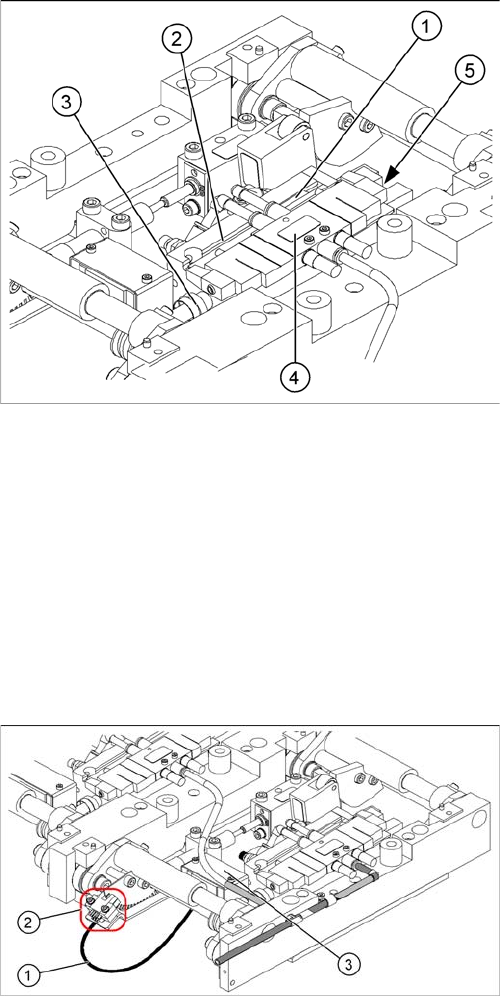
► Insert and fasten the new lifting table cylinder (2) and
install the piston rod (3).
► Move the lifting table by hand to its end position.
► Switch the machine on.
► Push the end position proximity switch (1) into the
guide rail until the LED lights up.
► Fix this position with the grub screw.
► Install the solenoid valve (4) and the lifting table plate.
Fasten any disconnected cables or hoses again, with
the cable ties.
► Check the speed of the lifting table and correct where
necessary.
Legend
1. Connection cable for the conversion board of the lift-
ing table
2. 2 x fork light barrier (position measuring system,
tracks A + B)
3. Conversion board of the lifting table (under the cover)
► Move the PCB conveyor to the position which gives
you best access to the lifting table.
► Move the Y gantries into the area outside the PCB
conveyor.
► Switch off the machine and secure it to prevent unau-
thorized reactivation.
► Loosen the screws fastening the lifting table plate and
remove the lifting table plate from the lifting table unit.
► Loosen the two screws (2) fastening the fork light bar-
rier.
► Remove the cover from the conversion board of the
lifting table (3).
► Unplug the lifting table conversion board.
► Fit the new fork light barrier and reconnect to the
electrical system.
Service Work
4.3.10 Replacing the Stepping Motor of the Width Adjustment System [00367174] PCB conveyor system
Service Manual SIPLACE D1/D1i/D2/D2i 101
4.3.10
4.3.10 Replacing the Stepping Motor of the Width Adjustment System [00367174]
Replacing the Stepping Motor of the Width Adjustment System [00367174]
Overview
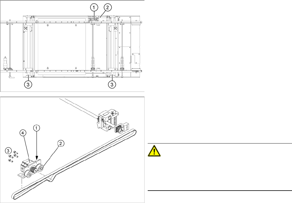
Legend
1. Width adjustment stepping motor
2. Toothed belt for the drive
3. Adjustment unit 1 and 2
Legend
1. Loosening the eccentric axle on the deflection pulley
2. Locknut on the eccentric axle
3. Fastening screws for stepping motor
4. Stepping motor [00367174-xx]
CAUTION!
Do not damage the toothed belt!
During the following removal and installation of the motor,
the toothed belt for the width adjustment drive must not
be stretched or kinked!
► Move the PCB conveyor to the position which gives
you best access to the stepping motor of the width
adjustment system.
► Move the Y gantries into the area outside the PCB
conveyor.
► Switch off the machine and secure it to prevent unau-
thorized reactivation.