00195376-05_SM_D1_D1i_D2_D2i_EN.pdf - 第103页
Service Work 4.3.11 Replacing the Limit Switc h for the End Position Width Ad justment System [0 0316831-xx] PCB conveyor system Service Manual SIPLACE D1/D1i/D2/D2i 103 4.3.11 4 . 3 . 1 1 R e p la c in g t h e L im it S…
Service Work
PCB conveyor system 4.3.10 Replacing the Stepping Motor of the Width Adjustment System [00367174]
102 Service Manual SIPLACE D1/D1i/D2/D2i
Removal/Installation
See also
6.7.1 Setting the Tension of the Conveyor Toothed Belt and the Width Adjustment Unit [ ➙ 261]
► Loosen the screws fastening the lifting table plate and
remove the lifting table plate from the lifting table unit.
► Loosen the eccentric axle (1) on the deflection pulley
and relieve the tension on the drive toothed belt (5).
CAUTION!
Parallelism of conveyor side: Toothed belt must not come
off!
When relaxing the toothed belt, make sure the belt does
not come off (skip) the toothed disks at the 2 adjustment
units. This would cause incorrect alignment of the adjust-
ment units. Secure these positions with a suitable tool
(screw clamp etc.)
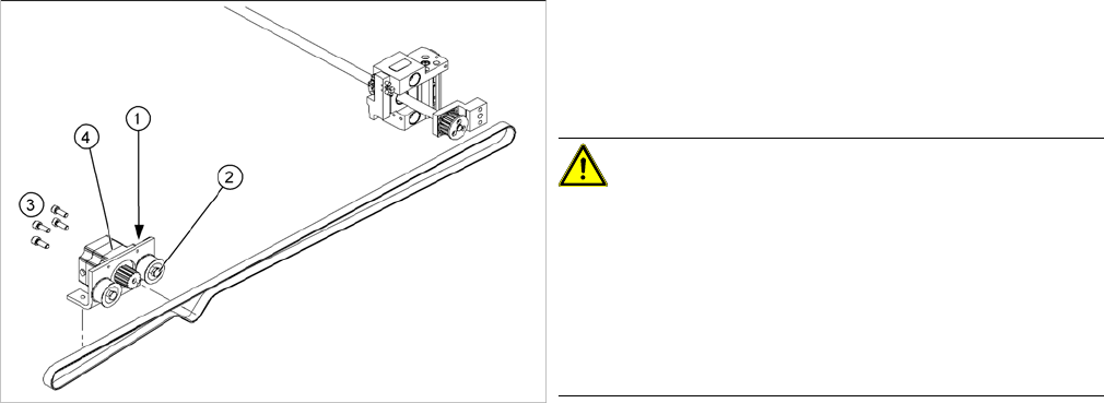
► Remove the 4 fastening screws (3) and then lift out
the stepping motor (4).
► Unplug the connection cable in the cable duct.
► Fit the new stepping motor and reconnect the system
to the electrical system.
► Tension the drive toothed belt.
► Position the measuring point of the belt tension de-
vice at the strand center (i.e. the longest distance be-
tween two toothed disks) of the conveyor toothed
belt.
► Adjust the tension of the drive toothed belt.
Service Work
4.3.11 Replacing the Limit Switch for the End Position Width Adjustment System [00316831-xx] PCB conveyor system
Service Manual SIPLACE D1/D1i/D2/D2i 103
4.3.11
4.3.11 Replacing the Limit Switch for the End Position Width Adjustment System [00316831-xx]
Replacing the Limit Switch for the End Position Width Adjustment System [00316831-
xx]
Overview
Parts
▪ Limit switch on the assembly tub
▪ Limit switch for width adjustment 1
▪ Limit switch for width adjustment 2
▪ Limit switch for width adjustment - at the conveyor
edge
The microswitch [00316831-xx] is used for all limit switch-
es.
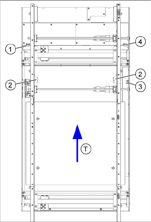
Legend
1. Limit switch 1 for width adjustment system of the ad-
justment unit
2. Limit switch for width adjustment system (for side)
3. Limit switch for assembly tub (for side)
4. Limit switch 2 for width adjustment system of the ad-
justment unit
▪ T = transport direction
Limit switch in placement area:
There are 2 limit switches below the conveyor sides, in
the placement area. The limit switch is designed to pre-
vent the conveyor edges hitting one another or the con-
veyor base.
Limit switch on the output conveyor:
In the vicinity of the output conveyors, you will find two
limit switches for the adjustment unit. They serve to se-
cure the transport area and to initialize the adjustment
unit during width adjustment.
Service Work
PCB conveyor system 4.3.12 Replacing the Solenoid Valve for the Adjustment Unit [00332940-xx]
104 Service Manual SIPLACE D1/D1i/D2/D2i
Removal/installation
4.3.12
4.3.12 Replacing the Solenoid Valve for the Adjustment Unit [00332940-xx] (applicable to modular PCB conveyor only)
Replacing the Solenoid Valve for the Adjustment Unit [00332940-xx] (applicable to
modular PCB conveyor only)
Overview
► Adjust the conveyor width, so that the required limit
switches can be easily accessed.
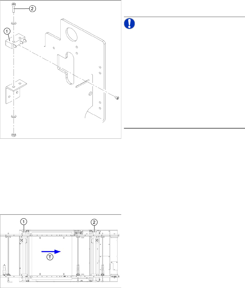
NOTICE!
The limit switches are preassembled and include cables.
However, if the limit switch itself is faulty, the wiring can
be unsoldered/soldered right at the switch in question.
Remove the heat-shrinkable sleeves and unsolder the
connection wires on the defective limit switch (1).
Loosen and remove the two screws (2) fastening the de-
fective limit switch.
If you have discovered a break in the connection cable
during a continuity check, this cable must be unthreaded
as far as the conversion board of the assembly tub and
unplugged there.This might be somewhat complicated
depending on the routing of cables inside the machine
base.
You may wish to contact SIPLACE service team regard-
ing this work.
► Fit the new limit switch and re-solder the connection
wires in the correct allocation.
Checking the position of the limit switch:
► Check the minimum and maximum width of the rele-
vant machine type and the parallelism of the convey-
or edges.
Parts
▪ Solenoid valve with cable, for adjustment unit 1 and 2
[00332940-xx]
Legend
1. Adjustment unit 1
2. Adjustment unit 2
▪ T = transport direction