00195376-05_SM_D1_D1i_D2_D2i_EN.pdf - 第107页
Service Work 4.3.14 Replacing the Proximity Switch for the Adjustment Unit [ 03040795 -xx] (applicable to modular PCB conveyor only) PCB conve yor sys tem Service Manual SIPLACE D1/D1i/D2/D2i 107 4.3.14 4 . 3 . 1 4 R e p…
Service Work
PCB conveyor system 4.3.13 Replacing the Cylinder Switch for the Adjustment Unit [03040796-xx]
106 Service Manual SIPLACE D1/D1i/D2/D2i
Removal/Installation
► Move the PCB conveyor to the position which gives
you best access to the adjustment system.
► Move the Y gantries into the area outside the PCB
conveyor.
► Switch off the machine and secure it to prevent unau-
thorized reactivation.
► Switch off the compressed air supply.
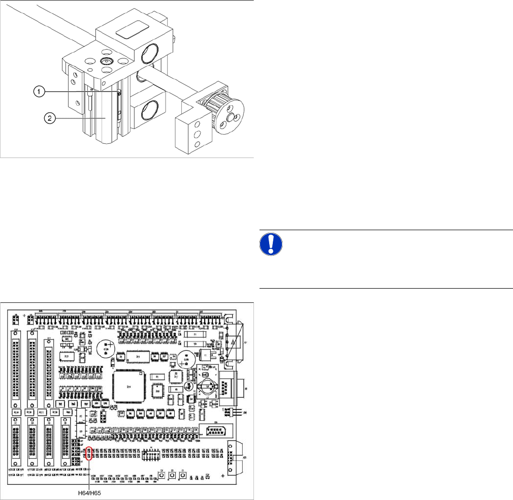
► Loosen the grub screw at the cylinder switch (1) and
push the cylinder switch out of the adjustment unit
guide rail (2).
► Unthread the connection cable as far as the conver-
sion board of the assembly tub.
► Run the connection cable of the new cylinder switch.
► Insert the new cylinder switch into the guide rail.
► Switch the machine on.
NOTICE!
The width adjustment system cylinder switch is set in en-
gaged mode.
TSP201
► Move the width adjustment system until the cylinder
switch switches - LED (H64/H65).
Engage the cylinder - i.e. the cylinders are moved to
the upper limit by the controls.
► Set the cylinder switch so that the LED lights up when
it is in engaged mode.
► Fix the position of the cylinder switch (2) with the grub
screw.
Service Work
4.3.14 Replacing the Proximity Switch for the Adjustment Unit [03040795-xx] (applicable to modular PCB conveyor only) PCB conveyor system
Service Manual SIPLACE D1/D1i/D2/D2i 107
4.3.14
4.3.14 Replacing the Proximity Switch for the Adjustment Unit [03040795-xx] (applicable to modular PCB conveyor only)
Replacing the Proximity Switch for the Adjustment Unit [03040795-xx] (applicable to
modular PCB conveyor only)
Overview
The proximity switch serves as a signal for controlling the pneumatic valve of the adjustment unit. Once
the switching point has been reached, the conveyor edge is connected via the short-stroke cylinder.
Removal/Installation
Parts
▪ Proximity switch for adjustment unit 1 and 2
[03040795-xx]
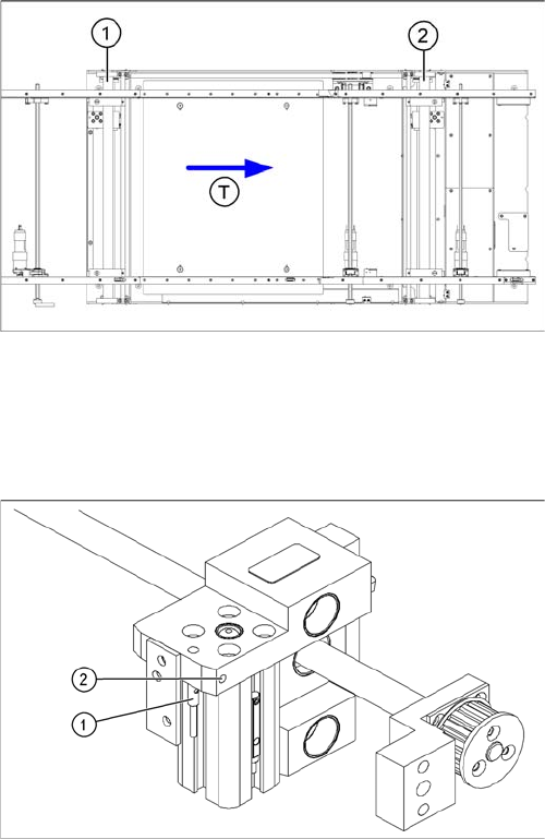
Legend
1. Adjustment unit 1
2. Adjustment unit 2
3. Transport direction
► Move the PCB conveyor to the position which gives
you best access to the adjustment system.
► Move the Y gantries into the area outside the PCB
conveyor.
► Switch off the machine and secure it to prevent unau-
thorized reactivation.
► Switch off the compressed air supply.
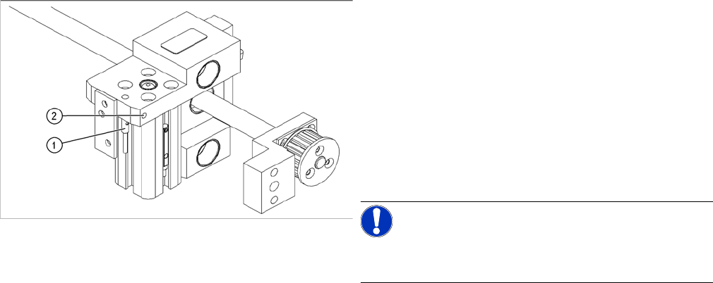
► Loosen the grub screw on the clamping device (1)
and unthread the connection cable as far as the con-
version board of the assembly tub.
► Fit the new proximity switch and reconnect the sys-
tem to the electrical system.
► Fix the proximity switch with the grub screw.
► Tighten the grub screw to a torque of 20 Ncm
(+3 Ncm). The proximity switch must be level with the
adjustment unit housing (2).
Service Work
PCB conveyor system 4.3.14 Replacing the Proximity Switch for the Adjustment Unit [03040795-xx]
108 Service Manual SIPLACE D1/D1i/D2/D2i
The switching point is set at the actuator on the conveyor
edge:
► Position the adjustment unit, with the help of the width
adjustment belt, so that the proximity switch can be
easily accessed.
► Place a 4/10mm distance gauge on the adjustment
unit and press this distance gauge against the adjust-
ment unit.
► Push the proximity switch upwards, as far as the stop
and tighten the fastening screw.
NOTICE!
Perform a width adjustment function test at all conveyor
sides.
► Use the SITEST program to calibrate the conveyor
edges.