00195376-05_SM_D1_D1i_D2_D2i_EN.pdf - 第113页
Service Work 4.4.1 Replacing the C&P6/12 Head (D1 D2) C&P6/12 Head Service Manual SIPLACE D1/D1i/D2/D2i 113 4.3.17.4 4 . 3 . 1 7 . 4 C o n v e y o r C o n t r o l T S P 2 0 1 [ 0 3 0 4 3 8 3 2 ] Conveyor Control …
Service Work
PCB conveyor system 4.3.17 Overview of the Electrical Components
112 Service Manual SIPLACE D1/D1i/D2/D2i
4.3.17
4.3.17 Overview of the Electrical Components
Overview of the Electrical Components
4.3.17.1
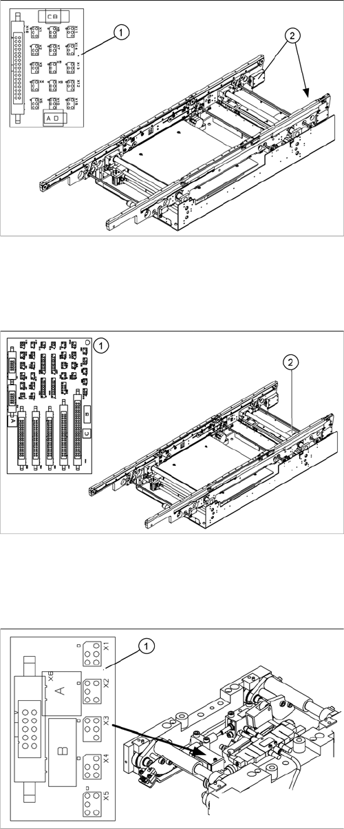
4.3.17.1 Conveyor Side Conversion Board [00359424]
Conveyor Side Conversion Board [00359424]
Overview
4.3.17.2
4.3.17.2 Conveyor Conversion Board [00359426]
Conveyor Conversion Board [00359426]
Overview
4.3.17.3
4.3.17.3 Lifting Table Conversion Board [00362766]
Lifting Table Conversion Board [00362766]
Overview
Legend
1. Conveyor edge conversion board
2. Cover
The conversion boards for the conveyor sides (1) are sit-
uated on the respective conveyor sides, under a cover
(2).
For terminal assignment details, please refer to the cur-
rent version of the detailed circuit diagrams for your
SIPLACE machine.
Legend
1. Conveyor conversion board
2. Cover
The conveyor conversion board (1) is situated in the vi-
cinity of the output conveyor, under the cover (2).
For terminal assignment details, please refer to the cur-
rent version of the detailed circuit diagrams for your
SIPLACE machine.
Legend
1. Lifting table conversion board
2. Cover
The lifting table conversion board (1) is situated on the
lifting table unit, under the cover (2).
For terminal assignment details, please refer to the cur-
rent version of the detailed circuit diagrams for your
SIPLACE machine.
Service Work
4.4.1 Replacing the C&P6/12 Head (D1 D2) C&P6/12 Head
Service Manual SIPLACE D1/D1i/D2/D2i 113
4.3.17.4
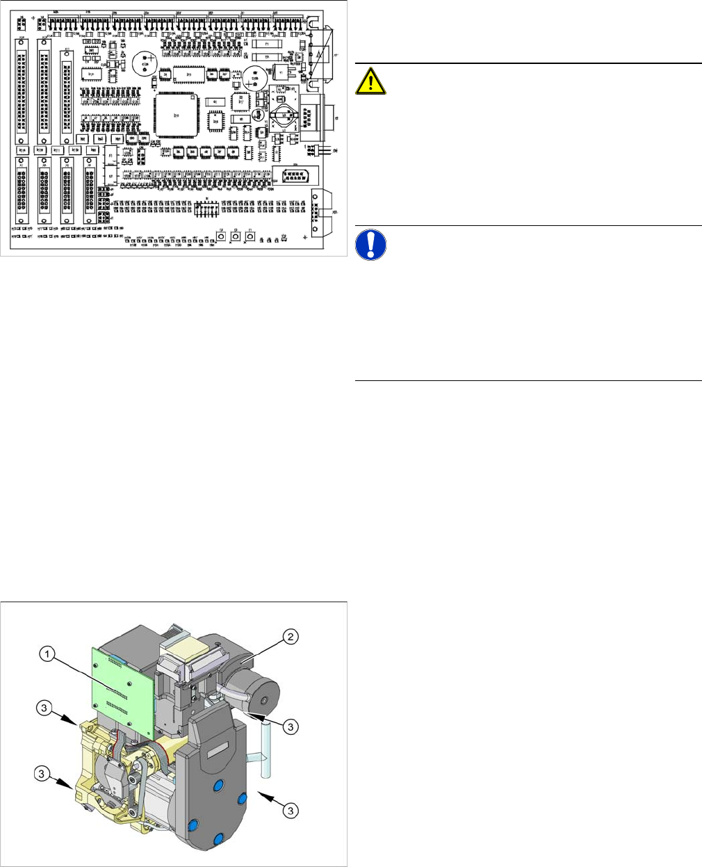
4.3.17.4 Conveyor Control TSP 201 [03043832]
Conveyor Control TSP 201 [03043832]
Overview
4.4
4.4 C&P6/12 Head
C&P6/12 Head
See also
3.5 DLM3 Collect&Place Head [ ➙ 35]
4.4.1
4.4.1 Replacing the C&P6/12 Head (D1 D2)
Replacing the C&P6/12 Head (D1 D2)
Overview
For terminal assignment details, please refer to the cur-
rent version of the detailed circuit diagrams for your
SIPLACE machine.
CAUTION!
Before removal
Before removing the assembly, perform data backup of
the TSP machine data in the SITEST menu "Conveyor –
Machine Data".
After replacing the assembly, restore the machine data in
the same menu.
NOTICE!
Firmware
After replacing the assembly you may need to perform a
firmware download (possible at any time in SITEST from
SC/MC 603.xx).
You may wish to contact SIPLACE service team regard-
ing this work.
Legend
1. Illumination controller
2. Vacuum distributor with vacuum measuring board
3. 4 x fastening screws
Item numbers
C&P head DLM3 with 12 segments (C&P12 head)
▪ Complete, with sleeves [03041228-xx]
▪ Without sleeves [03047768-xx]
C&P head DLM3 with 6 segments (C&P6 head)
▪ Complete, with sleeves [03041229-xx]
▪ Without sleeves [03048341-xx]
Service Work
C&P6/12 Head 4.4.1 Replacing the C&P6/12 Head (D1 D2)
114 Service Manual SIPLACE D1/D1i/D2/D2i
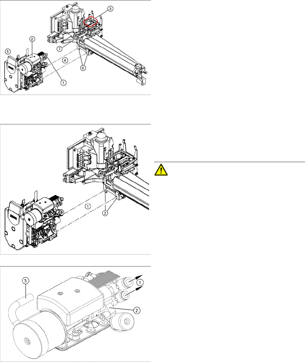
Removal
Installation
See also
6.5.1 Calibrating the C&P Head and Cameras [ ➙ 232]
► Remove the compressed air hoses (1) from the pneu-
matic coupling of the vacuum generator (2).
► Loosen the press-fit connection to the C&P head
((5) from the gantry head distributor ((3) = installation
position).
► Loosen the 4 screws (4) fastening the C&P head.
► Unplug the hose to the vacuum distributor connection
disk.
► Carefully pull the C&P head away from the parallel
pins (5) on the head mount (6) and remove the head
from the machine.
► Make sure that all contact surfaces and pins are
clean.
► Carefully move the C&P head towards the head
mount (2).
CAUTION! Make sure that the cables and sili-
con hoses are not pinched.
► Make sure that the parallel pins on the head mount
slide into the holes drilled into the back part of the
C&P head.
► Carefully push the C&P head towards the head
mount until it lies flat against it.
► Fix the C&P head with the 4 screws provided (1).
► Reconnect the compressed air hoses (1) to the pneu-
matic coupling of the vacuum generator (2) and re-
store all hose connections (3).
► Reconnect to the electricity system.
► Use the SITEST program to calibrate the C&P head.