00195376-05_SM_D1_D1i_D2_D2i_EN.pdf - 第119页
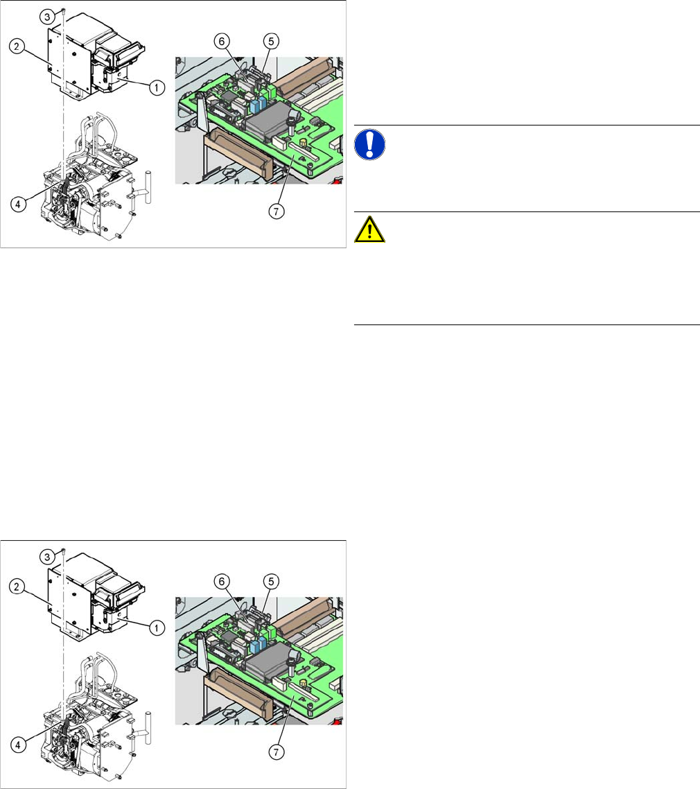
Service Work 4.4.4 Replacing the Intermediate Distributor C&P6/12 Head Service Manual SIPLACE D1/D1i/D2/D2i 119 4.4.4 4 . 4 . 4 R e p la c in g t h e I n t e r m e d ia t e D is t r ib u t o r Replacing the Intermedi…
Service Work
C&P6/12 Head 4.4.3 Replacing the Component Camera (D Series) [03014449-xx]
118 Service Manual SIPLACE D1/D1i/D2/D2i
4.4.3
4.4.3 Replacing the Component Camera (D Series) [03014449-xx]
Replacing the Component Camera (D Series) [03014449-xx]
Removal/Installation
Installation
See also
4.4.22 Press Fit Connections with Fixture Clips on the Vision Board (D Series) [ ➙ 157]
The component camera must be replaced as a complete
unit. This consists of the lens system, camera, amplifier,
illumination planes and "illumination controller" board.
Article numbers
▪ SST28 [03014449-xx]
▪ SST29 [03018637-xx]
NOTICE! You may need to completely disman-
tle the front part of the head (4), so that the components
can be more easily accessed.
CAUTION! Do not damage the fixture clips!
To disconnect the component and PCB camera connec-
tions, you need to open the fixture clips by applying pres-
sure to the side of the connector.
For details see section xxx
► Disconnect the flat ribbon cable holders (5) at the Vi-
sion board (7) of the gantry head distributor.
► Pull both flat ribbon cable connectors (6) off the Vi-
sion board of the gantry head distributor (2).
► Loosen the four screws (3) holding the component
camera.
► Carefully lift off the component camera (1).
► Make sure that all contact surfaces are clean.
► Place the holes in the camera on the parallel pins (4).
► Carefully position the camera on the C&P head, until
the camera plinth lies flat on the contact surface of
the front part of the C&P head.
► Fix the camera in place with the four screws provided
(3).
► Fit the front part of the C&P head (4).
► Reconnect the flat ribbon cables (6) to the Vision
board (7) of the gantry head distributor.
► Refit the flat ribbon cable strain relief (5). This rees-
tablishes the ground connection.
► Start the machine.
► Use the SITEST program to calibrate the C&P head.
Service Work
4.4.4 Replacing the Intermediate Distributor C&P6/12 Head
Service Manual SIPLACE D1/D1i/D2/D2i 119
4.4.4
4.4.4 Replacing the Intermediate Distributor
Replacing the Intermediate Distributor
Parts, equipment and tools
▪ Intermediate distributor DLM2/DLM3 [00330648-xx] or
intermediate distributor DLM4 [03082809-xx]
Removal/installation
The following supply voltages and signals are routed by the intermediate distributor to the individual
placement head modules or to the head board:
► Please observe the ESD regulations for the following
work and use an ESD ground strap.
► Loosen the four fastening screws and remove the
cover (1), by pulling these off the 4 snap fasteners.
► Undo the four spacer bolts (3) and tilt the intermedi-
ate distributor (2) a little.
Position of the sockets
1. Front of the intermediate distributor
2. Back of the intermediate distributor
▪ U4 = pressure sensor
► Carefully disconnect the hose from the pressure sen-
sor (U4).
► Disconnect the connection plugs from their slots. Re-
fer to the circuit diagram folder for the relevant ma-
chine.
► Remove the intermediate distributor.
► Restore connections X1......X12.
► Push the hose onto the pressure sensor tube (U4).
► Fasten the intermediate distributor.
NOTICE
Settings, machine data
► No settings are required.
► The axis machine data can be saved in the memory of this board using the Head Exchange
option in the menu.
Service Work
C&P6/12 Head 4.4.5 Replacing the Turning Station (D Series) [00341780-xx]
120 Service Manual SIPLACE D1/D1i/D2/D2i
See also
6.5.2 PCB Boards on the 6/12 C&P Head [ ➙ 233]
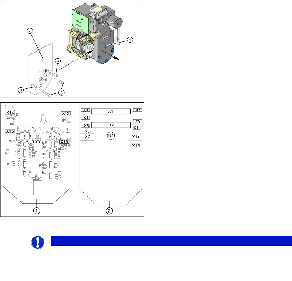
4.4.5
4.4.5 Replacing the Turning Station (D Series) [00341780-xx]
Replacing the Turning Station (D Series) [00341780-xx]
Removal/Installation
Connectors Description
X1, 40-pole Connected to plug X14 on the head board
▪ Voltage supply, tacho and track signals for the Z axis drive
▪ Signal from light barrier "Z axis in top position"
▪ Signal from light barrier "Z axis in bottom position" (sensor stop signal)
▪ Control signal for the air blast valve
▪ Supply voltage +5 VDC, ±15 VDC
▪ Reference point signal for the DP axis
▪ Track signals for the DP axis
X2, 40-pole Connected to plug X13 of the gantry head distributor
▪ Voltage supply and track signals for the star axis drive
▪ Reference point for the star axis
▪ Analog air blast pressure value
▪ Supply voltages +5 VDC, ±15 VDC, +24 VDC
X3, 10-pole Connection for the Z motor and Z tacho signal (Tacho signal is not use on the HF
machine)
X4, 10-pole Connection for the Z axis track signals
X5, 10-pole Connection for the star motor
X6, 6-pole Connection for the air blast valve
X7, 10-pole Connection for the DP axis track signals
X10, 10-pole Connection for the "Z axis up" signal (positioning unit)
X11, 8-pole Connection for the light barrier "Z axis down" signal (sensor stop signal)
X12, 10-pole Connection for the star axis track signals
X13, 10-pole Test connection for the Z axis track signals
X14, 10-pole not used
X15, 10-pole Test connection for the star axis track signals
X16, 10-pole Test connection for the DP axis track signals
Legend
1. Turning station
2. Fastening screw for turning station
NOTICE! The head does not need to be re-
moved when dismantling the turning station.
► Switch off the machine and secure it to prevent unau-
thorized reactivation.
► Open the strain relief at the gantry head distributor.
► Disconnect the motor cable and flat ribbon cable from
the sockets on the gantry head distributor.
1
2