00195376-05_SM_D1_D1i_D2_D2i_EN.pdf - 第139页
Service Work 4.4.12 Replacing the Z Ax is Toothed Belt [00334936 -xx] C&P6/12 Head Service Manual SIPLACE D1/D1i/D2/D2i 139 See also 6.5.6 Setting the Z axis Belt Tension [ ➙ 235] NOTICE! Make sure that bot h end…
Service Work
C&P6/12 Head 4.4.12 Replacing the Z Axis Toothed Belt [00334936-xx]
138 Service Manual SIPLACE D1/D1i/D2/D2i
4.4.12
4.4.12 Replacing the Z Axis Toothed Belt [00334936-xx]
Replacing the Z Axis Toothed Belt [00334936-xx]
Removal
Installation
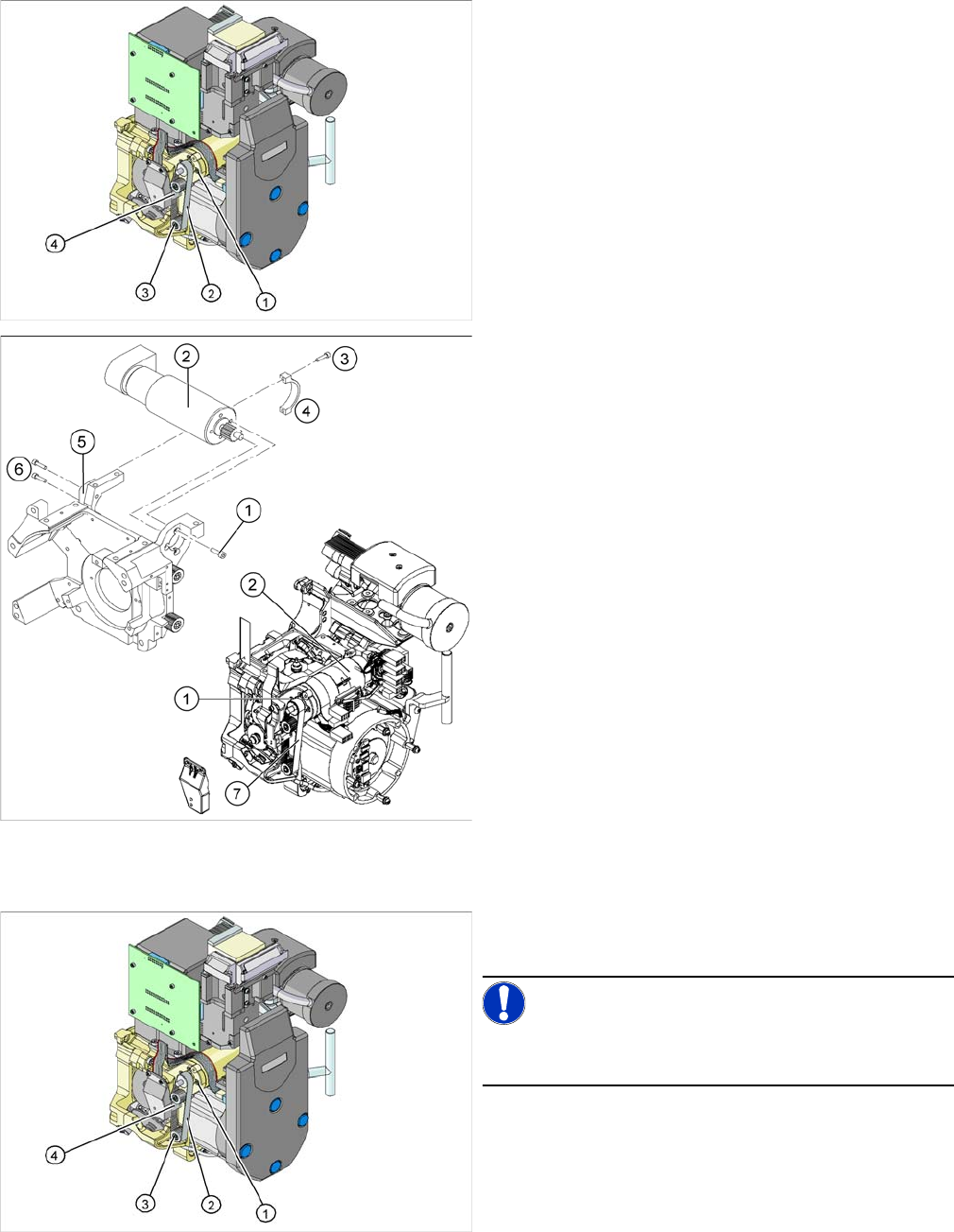
1. Z axis drive
2. Z axis toothed belt
3. 2 x deflection wheel / DLM3
4. Tension jack (Z axis clamping device)
► Switch off the machine and secure it to prevent unau-
thorized reactivation.
► Loosen the two screws fastening the tension jack (3).
► Loosen the two M2.5x12 hexagon socket-head
screws (3) on the motor clamp fitting (4).
► Loosen the two M3x14 hexagon socket-head screws
(6) on the motor clamp fitting (5).
► Slightly loosen the four M3x5 hexagon socket-head
screws (1).
► Remove the toothed belt (7).
► Place the new toothed belt over the pinion of the Z
axis drive and the deflection wheels.
NOTICE!
Make sure that the teeth of the toothed belts engage in
the teeth of the pinion and deflection pulleys.
► Fit the tension jack (4) with the two fastening screws,
to the toothed belt.
Service Work
4.4.12 Replacing the Z Axis Toothed Belt [00334936-xx] C&P6/12 Head
Service Manual SIPLACE D1/D1i/D2/D2i 139
See also
6.5.6 Setting the Z axis Belt Tension [ ➙ 235]
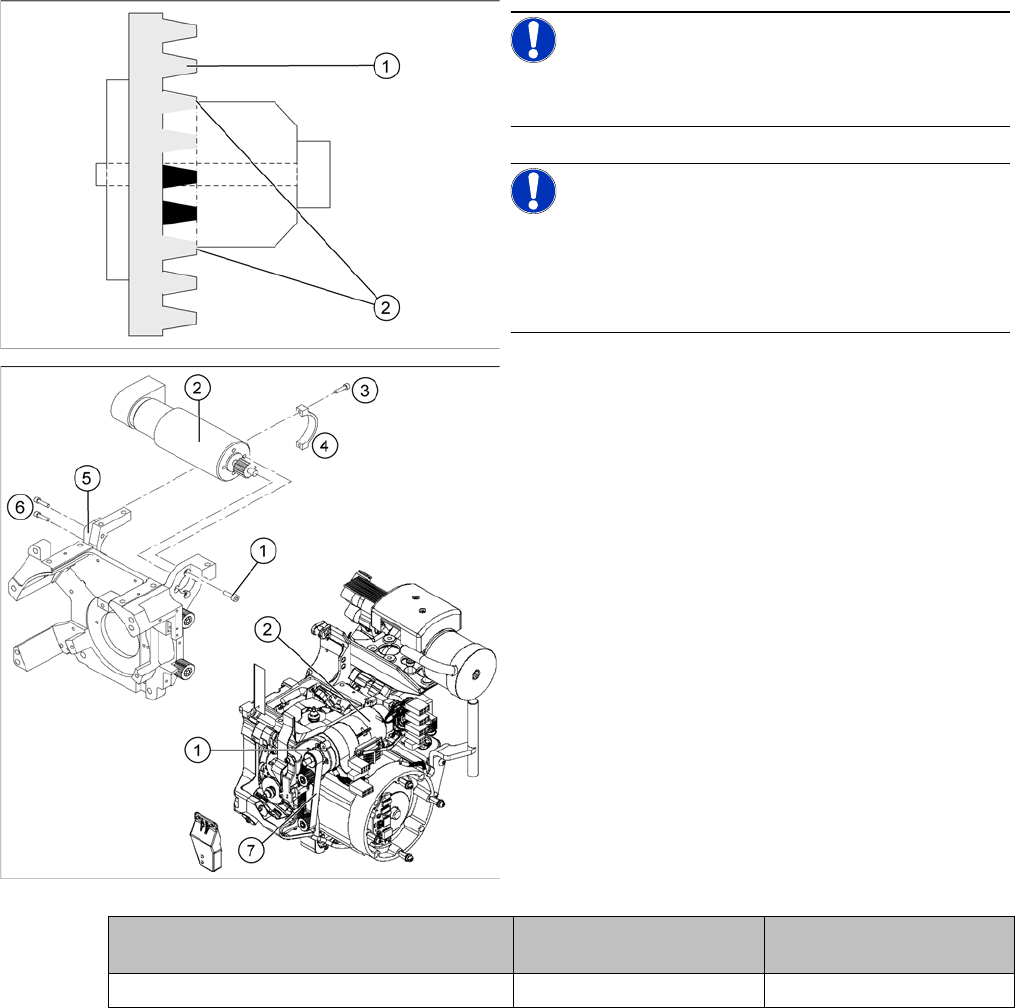
NOTICE!
Make sure that both ends (2) of the tension jack lie on the
teeth of the toothed belt (1) .
NOTICE!
New tension jack
A new tension jack (fitted from 10/2007) has a profile
which engages with the toothed belt and therefore en-
sures a more reliable clamping.
► Loosely screw in the four M3x5 hexagon socket-head
screws (1) on the Z axis drive unit (2).
► Tension the Z axis toothed belt (7) by pushing the Z
axis drive unit upwards.
► Check the toothed belt tension with the belt tension
measuring device.
► Tighten the two M3x14 hexagon socket-head screws
(6) to fix the motor clamp (5).
► Fix the motor clamp 2 (4) with the two M2.5x12 hex-
agon socket-head screws (3).
► Now tighten the hexagon socket-head screws on the
Z axis drive unit and the motor clamp.
► Check the Z axis top stop with the setting gauge.
Frequency in Hz Before continuous opera-
tion run
After continuous operation
run
Toothed belt T2 / DLM3 on the Z axis 280 +/- 10 280 +/- 10
Service Work
C&P6/12 Head 4.4.13 Replacing the "Z Axis Down" Sensor [00321524-xx]
140 Service Manual SIPLACE D1/D1i/D2/D2i
4.4.13
4.4.13 Replacing the "Z Axis Down" Sensor [00321524-xx]
Replacing the "Z Axis Down" Sensor [00321524-xx]
Removal
Installation
Adjusting the "Z axis down" sensor
► Set the distance between the white sleeve ring and the light barrier to 0.95 -1.15 mm.
⇨ Use a test probe or drill (diameter 1.0 mm) for this.
⇨ Check the distance with a test probe or drill (diameter 1.2 mm). – This drill should not fit!
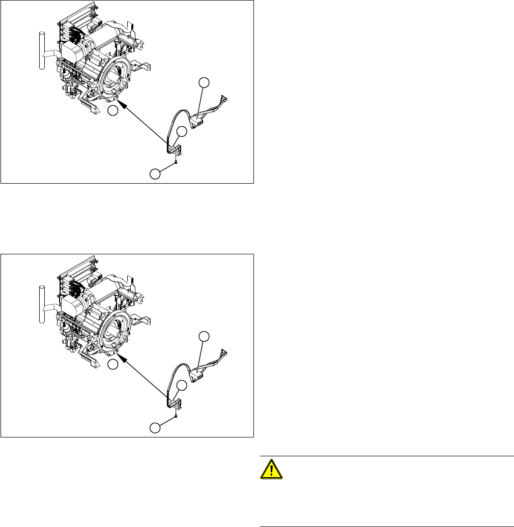
1. "Z axis down" sensor
2. Fixtures for sensor
3. Plug for intermediate distributor
► Dismantle the front part of the C&P head.
► Dismantle the star.
► Remove the plug from the slot on the intermediate
distributor.
► Push the Z axis down.
► Loosen the screws holding the sensor (2).
► Remove the cable clamps on the driver arm and star
motor.
► Carefully pull the sensor and cable out of the front
part of the C&P head and remove the plug (3) from
the socket on the intermediate distributor.
1
1
3
2
► Thread the sensor cable from the Z axis into the front
part of the C&P head.
► Fix the sensor (1) in position with the screw provided
(2) and initially screw loosely into the jaw of the Z ax-
is.
► Fix the cable into place with the cable clamps.
► Check how the cable is run inside the front part of the
C&P head:
⇨ If the Z axis has been pushed right out, the cable
should lie loosely around the housing for the star
drive shaft. The cable must NOT be pulled tight.
⇨ If the Z axis is pushed right in, the cable should run
freely inside the front part of the C&P head, with-
out touching the rotary encoder for the DP axis.
CAUTION!
Check how the cables are run!
If the radius of the curvature is too small, the Z axis could
jam or the light barrier cable could break.
► Once the cable is run in line with the required condi-
tions, fix it in place with the angled clips.
► Connect the cable plug to the slot on the intermediate
distributor.
1
1
3
2