00195376-05_SM_D1_D1i_D2_D2i_EN.pdf - 第141页
Service Work 4.4.14 Replacing the Complete Z Axis [03001959-xx] C&P6/12 Head Service Manual SIPLACE D1/D1i/D2/D2i 141 ► Fix the light barrier in place with the two screws provided. ► Fit and adjust the star. ► Fit th…
Service Work
C&P6/12 Head 4.4.13 Replacing the "Z Axis Down" Sensor [00321524-xx]
140 Service Manual SIPLACE D1/D1i/D2/D2i
4.4.13
4.4.13 Replacing the "Z Axis Down" Sensor [00321524-xx]
Replacing the "Z Axis Down" Sensor [00321524-xx]
Removal
Installation
Adjusting the "Z axis down" sensor
► Set the distance between the white sleeve ring and the light barrier to 0.95 -1.15 mm.
⇨ Use a test probe or drill (diameter 1.0 mm) for this.
⇨ Check the distance with a test probe or drill (diameter 1.2 mm). – This drill should not fit!
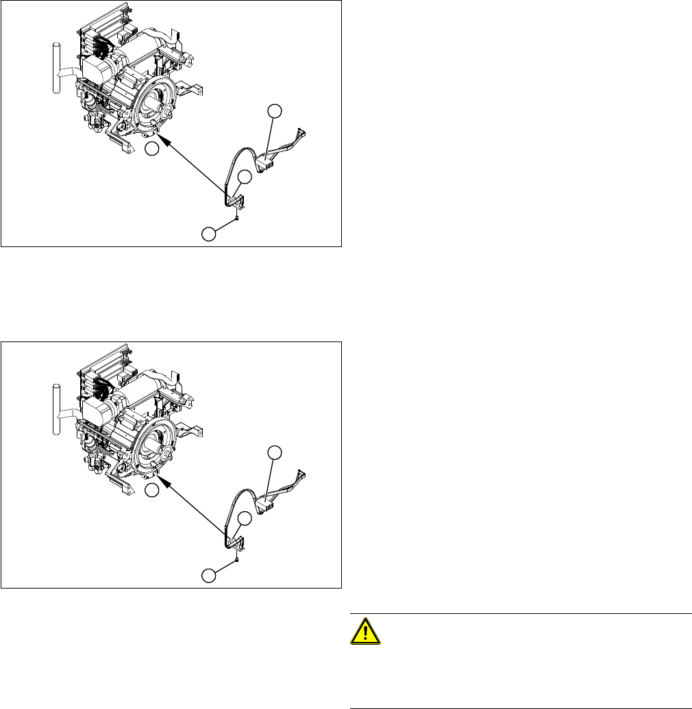
1. "Z axis down" sensor
2. Fixtures for sensor
3. Plug for intermediate distributor
► Dismantle the front part of the C&P head.
► Dismantle the star.
► Remove the plug from the slot on the intermediate
distributor.
► Push the Z axis down.
► Loosen the screws holding the sensor (2).
► Remove the cable clamps on the driver arm and star
motor.
► Carefully pull the sensor and cable out of the front
part of the C&P head and remove the plug (3) from
the socket on the intermediate distributor.
1
1
3
2
► Thread the sensor cable from the Z axis into the front
part of the C&P head.
► Fix the sensor (1) in position with the screw provided
(2) and initially screw loosely into the jaw of the Z ax-
is.
► Fix the cable into place with the cable clamps.
► Check how the cable is run inside the front part of the
C&P head:
⇨ If the Z axis has been pushed right out, the cable
should lie loosely around the housing for the star
drive shaft. The cable must NOT be pulled tight.
⇨ If the Z axis is pushed right in, the cable should run
freely inside the front part of the C&P head, with-
out touching the rotary encoder for the DP axis.
CAUTION!
Check how the cables are run!
If the radius of the curvature is too small, the Z axis could
jam or the light barrier cable could break.
► Once the cable is run in line with the required condi-
tions, fix it in place with the angled clips.
► Connect the cable plug to the slot on the intermediate
distributor.
1
1
3
2
Service Work
4.4.14 Replacing the Complete Z Axis [03001959-xx] C&P6/12 Head
Service Manual SIPLACE D1/D1i/D2/D2i 141
► Fix the light barrier in place with the two screws provided.
► Fit and adjust the star.
► Fit the front part of the C&P head.
► Check the sensor function.
See also
4.4.2 Removal/Installation of Head Front Part [ ➙ 115]
4.4.17 Replacing the Star [ ➙ 144]
6.5.1 Calibrating the C&P Head and Cameras [ ➙ 232]
4.4.14
4.4.14 Replacing the Complete Z Axis [03001959-xx]
Replacing the Complete Z Axis [03001959-xx]
► Move the changeover table out of the machine.
► Switch off the machine.
► Remove the front part of the C&P head. (See "4.4.2
Removal/Installation of Head Front Part" [ ➙ 115].)
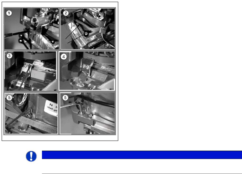
► (1) Dismantle the light barrier under the Z axis, by
loosening the two M1.6x3 DIN 84 screws.
► (2) Carefully pull the cable out of the cable duct until
it lies loosely.
► (3) Loosen the connection between the driver arm
and driver bracket by removing the two M2x14 DIN
912 screws.
► (4) Pull the driver arm, together with the centering pin,
out of the driver bracket and move the driver arm into
the stop position in the raceway.
► (5) Remove the three screws holding the Z axis in
place (2x M3x14, 1x M3x4).
NOTICE
Replacing the Z axis on the DLM3/DLM4
We recommend replacing the complete Z axis after approx. 100 million placements.
Service Work
C&P6/12 Head 4.4.15 Replacing the Forced Air Unit [00367793-xx]
142 Service Manual SIPLACE D1/D1i/D2/D2i
Installation
4.4.15
4.4.15 Replacing the Forced Air Unit [00367793-xx]
Replacing the Forced Air Unit [00367793-xx]
Removal
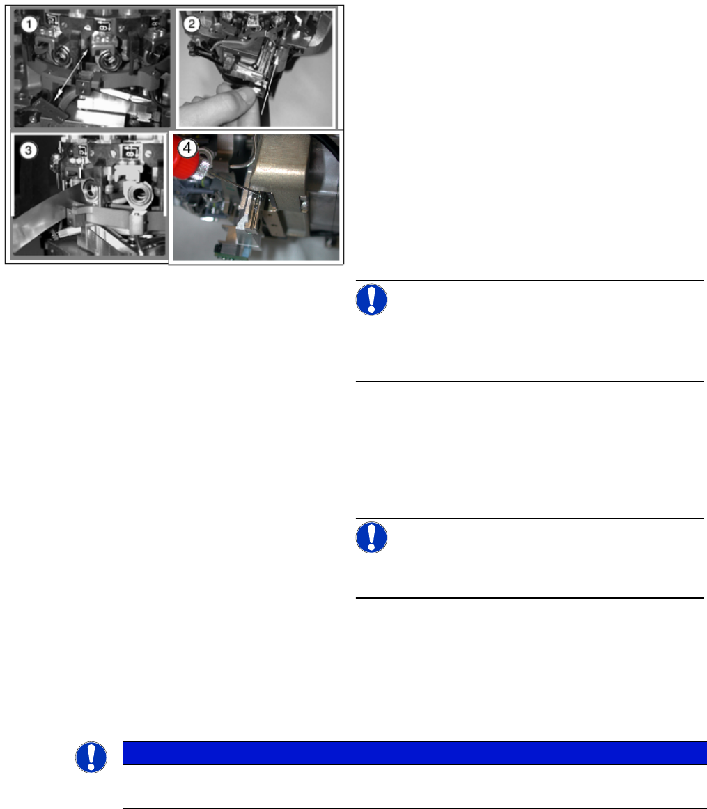
► (1) Rotate the star into the position shown and then
remove the Z axis from its guidance by taking hold of
the mounting plate.
Clean the contact surface with SIPLACE cleansing
tips and ethanol.
► (2) Push the new Z axis guide into the groove provid-
ed.
Press the reference edge (inner side) of the Z axis
into the groove and fix the Z axis with the screws pro-
vided.
► (3) Use the feeler gauge to check the gap between
the jaws and the side edges of the circular arc guide.
The gap may be between 0.02 and 0.03 mm.
Adjust the jaws if necessary.
Reassemble the placement head as follows.
NOTICE!
The board must be fitted centered to the jaws.
Make sure that the board does not rub against the frame
(check with gauge if necessary).
Complete the following step at every second service in-
terval for the head:
► (4) Use the mini oiler device to apply a small amount
of oil [00367071-xx] to the drilling provided.
Make sure that there is not too much oil coming out
of this hole.
NOTICE!
Where dirt is not excessive, the oil can be directly applied
to the rail.
Refit the front part of the C&P head. (See "4.4.2 Remov-
al/Installation of Head Front Part" [ ➙ 115].)
NOTICE
DLM 4
In DLM4, the hose for the reject circuit is cut off and the one-way restrictor is closed.