00195376-05_SM_D1_D1i_D2_D2i_EN.pdf - 第153页
Service Work 4.4.21 Checking the Cable Routing C&P6/12 Head Service Manual SIPLACE D1/D1i/D2/D2i 153 ▪ Position cable ties correctly: Cables ties should be positioned s o that the cables can be fast ened properly and…
Service Work
C&P6/12 Head 4.4.20 Replacing the Control Board for the Nozzle Changer 6/12 [00317353-xx]
152 Service Manual SIPLACE D1/D1i/D2/D2i
4.4.20
4.4.20 Replacing the Control Board for the Nozzle Changer 6/12 [00317353-xx]
Replacing the Control Board for the Nozzle Changer 6/12 [00317353-xx]
Overview
4.4.21
4.4.21 Checking the Cable Routing
Checking the Cable Routing
SIPLACE D1/D2 as example
Correct cable routing to and from the placement head is essential for long and accurate operation.
The high acceleration of the gantries can cause wear and damage to the connection leads.
▪ Cover unused connector strips with plastic caps:
Flat ribbon cables and coax leads can be damaged by unused connector strips. Make sure you at-
tach plastic caps.
Use dummy plugs for this [00368931-xx].
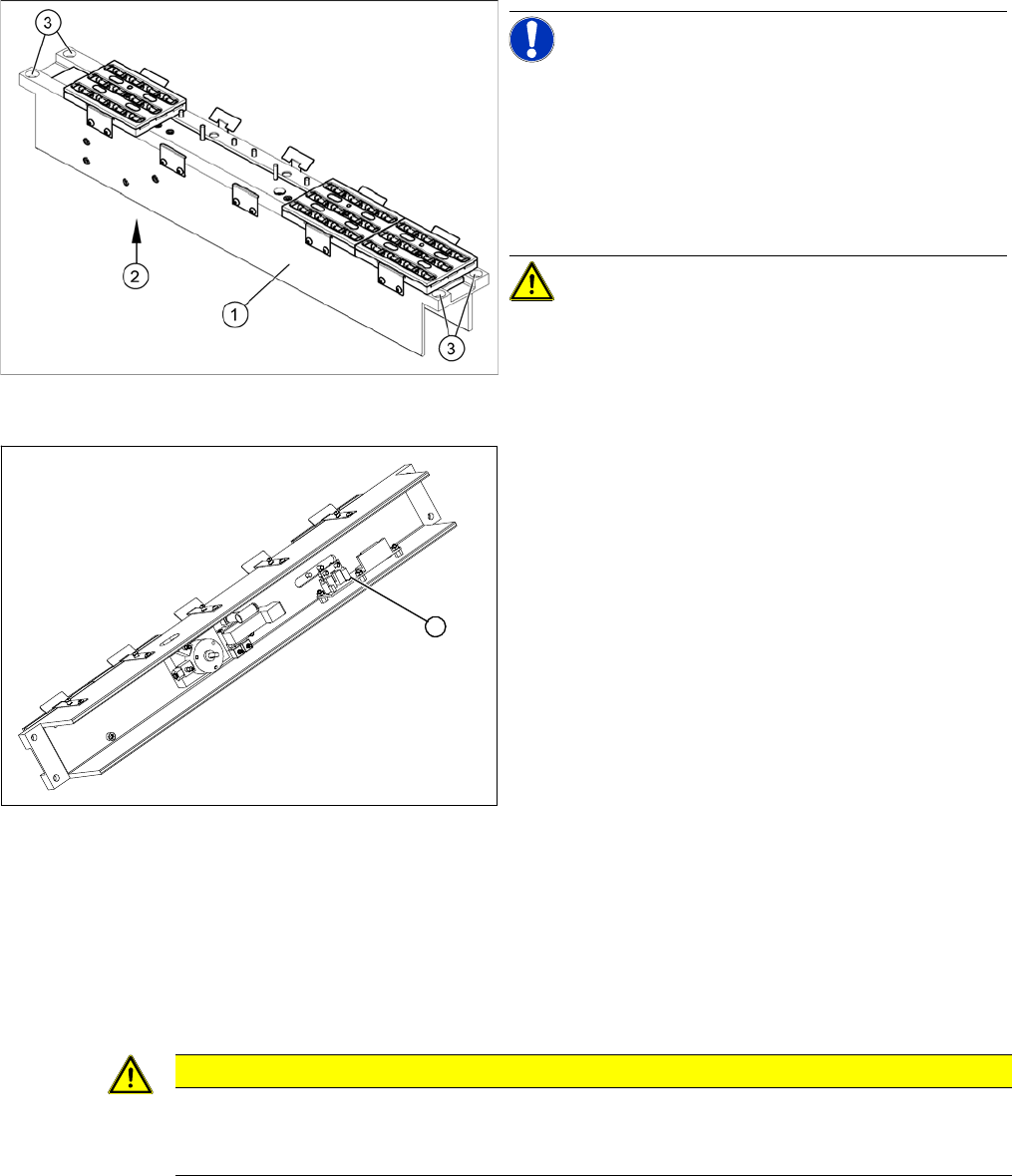
Nozzle changer for C&P12 (D4 shown as example)
NOTICE! The D1/D2 nozzle changers are just 1
magazine longer than those used for the D4. The struc-
ture is identical.
Legend
1. Nozzle changer 12 segments
2. Control board (installed on the underside)
3. 4 x fastening screws
CAUTION! The control board is also used for the
6-segment nozzle changer.
► Remove the nozzle changer from the machine. The
control board is situated on the underside of the noz-
zle changer.
Nozzle changer for C&P12 - viewed from below (D4
shown as example)
► Disconnect the control board (1) from the electrical
system.
► Loosen the fastening screws and remove the control
board .
► Fit the new control board and reconnect to the elec-
trical system.
► Fit the nozzle changer in the machine.
► Measure the nozzle changer with SITEST.
1
CAUTION
Check the cable routing!
Incorrect cable routing or poor fixture of the connection cables can cause mechanical damage.
This can then lead to malfunctions, non-reproducable errors and machine standstill.
Service Work
4.4.21 Checking the Cable Routing C&P6/12 Head
Service Manual SIPLACE D1/D1i/D2/D2i 153
▪ Position cable ties correctly:
Cables ties should be positioned so that the cables can be fastened properly and are guided past
any sharp edges.
▪ Cable clamps for flat ribbon cable:
If run together, narrow flat ribbon cables should be placed under wider ones.
The cables should not cross over one another under the clamp.
4.4.21.1
4.4.21.1 Cable Routing for Gantry Head Distributor Board
Cable Routing for Gantry Head Distributor Board
SIPLACE D1/D2 as example
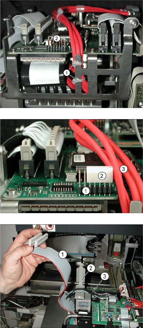
Position cable ties correctly.
The coax camera cables to the gantry head distributor
need to be fixed with cables ties at the side.
The diagram shows the optimum position (1) for two ca-
ble ties, so that the cables do not touch the connector
strip (2).
▪ However, the connector strip (2) should still be fitted
with a dummy plug for safety purposes.
Using a dummy plug
▪ The connector strip (1) needs to be covered.
▪ Use the "dummy plug" [00368931-xx] (2) for this.
▪ Position the dummy plug (2) so that the connectors
pointing towards the cable (3) to be protected are
covered.
Wide flat ribbon cables are run above narrow ones
▪ If run together, narrow flat ribbon cables (3) must be
run under wider ones (1).
▪ Finally, carefully close the clamp.
Service Work
C&P6/12 Head 4.4.21 Checking the Cable Routing
154 Service Manual SIPLACE D1/D1i/D2/D2i
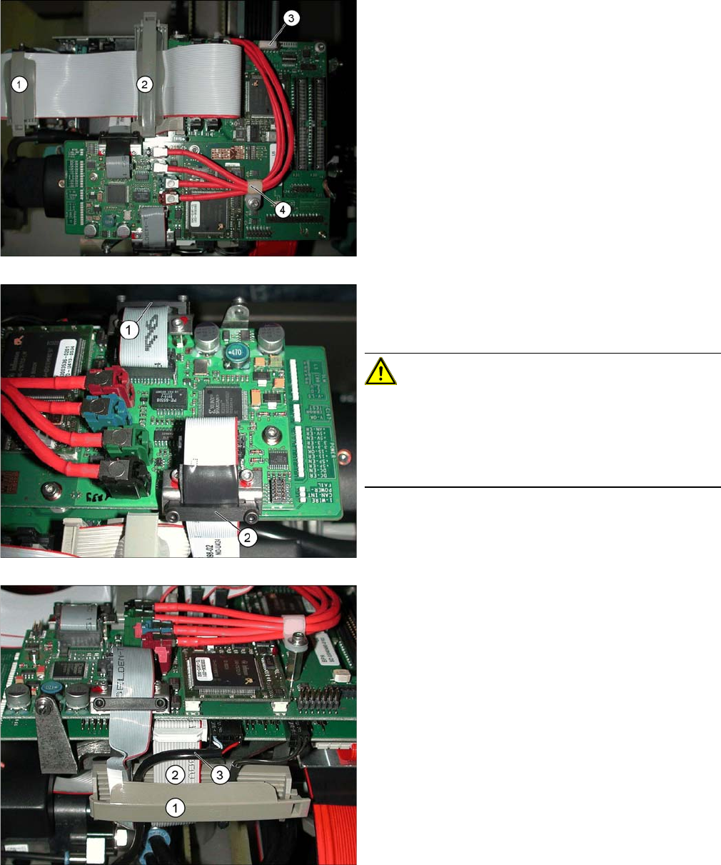
Cable clamps for flat ribbon cable
▪ The flat ribbon cable must be fixed with the clamps
(1) and (2). Use the "flat ribbon cable fastening
FCM3" 2 [03001829S01] for this.
▪ The narrower camera cable should be run under the
wide flat ribbon cable.
▪ Unused connector strips should be covered with a
plastic cap (3).
▪ The cable clamp (4) for the coax camera cables
needs to be fixed into place.
Fixture clamps
▪ The camera cables need to be fastened with fixture
clamps before the connector plugs.
CAUTION! Do not pinch the cables!
If the camera cable is pinched at the side and damaged,
this could lead to a short circuit (40V) and, for example,
could damage the DC/DC converter.
Always fix cables with a clamp in the middle (2). Do not
overtighten the screws of the fixture clamp.
▪ Check that the clamps are fixed properly at points (1)
and (2).
Securing the connector strip with a cable clamp
▪ To ensure reliable connections, use a cable clamp
(1).
▪ Inside the cable clamp, the cables should be run next
to one another, see also items (2), (3).