00195376-05_SM_D1_D1i_D2_D2i_EN.pdf - 第161页
Service Work 4.5.1 Replacing the Pi ck&Place Head [03033628-xx] Pick&Place Head Service Manual SIPLACE D1/D1i/D2/D2i 161 Removal/Installation Replacing the P&P head ► Disconnect the gantry from the electrical…
Service Work
Pick&Place Head 4.5.1 Replacing the Pick&Place Head [03033628-xx]
160 Service Manual SIPLACE D1/D1i/D2/D2i
4.5
4.5 Pick&Place Head
Pick&Place Head
4.5.1
4.5.1 Replacing the Pick&Place Head [03033628-xx]
Replacing the Pick&Place Head [03033628-xx]
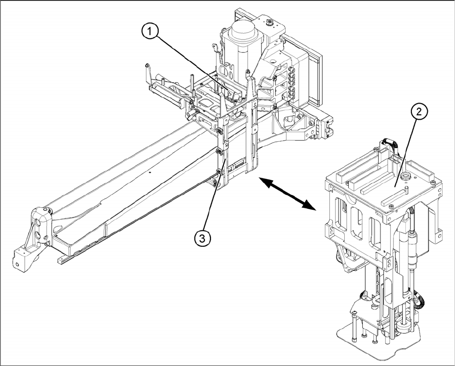
Overview
► Move the component trolley out of the machine.
► Switch off the machine.
► Move the P&P head to a suitable working position.
► Detach the compressed air connection from the P&P head to the vacuum distributor (1).
► Unplug the flat ribbon cable from the main board (2) on the P&P head.
The P&P head is fixed with 4 screws to the head mount (3) and is positioned with two pins.
Service Work
4.5.1 Replacing the Pick&Place Head [03033628-xx] Pick&Place Head
Service Manual SIPLACE D1/D1i/D2/D2i 161
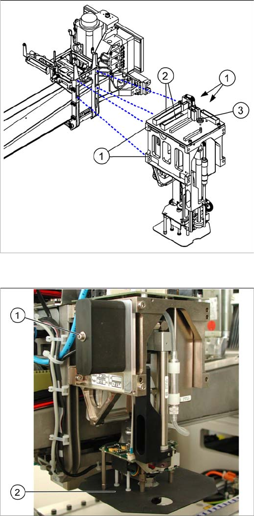
Removal/Installation
Replacing the P&P head
► Disconnect the gantry from the electrical (2) and com-
pressed air (3) systems.
► Loosen the 4 fastening screws (1) with an Allen
wrench which is at least 150 mm long. (not a ball-
head Allen wrench!)
► Pull the head off of the locating pins.
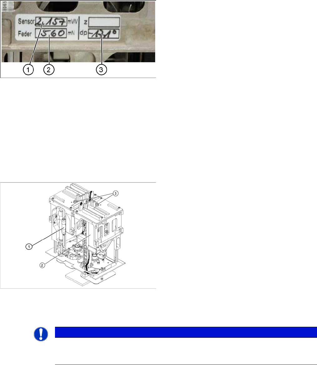
► Make a note of the force values for the new head.
These force values can be found on a label at the side
of the head.
► Fit the new head.
► Reconnect the system to the electrical and com-
pressed air systems.
Legend
If you need to replace the placement head, refit the fol-
lowing parts from the old P&P head:
1. Silencer for the vacuum generator
2. Panel for IC camera
Service Work
Pick&Place Head 4.5.2 Replacing the Vacuum Control System, Filter and Additional Volume
162 Service Manual SIPLACE D1/D1i/D2/D2i
Entering the force values for the new module
4.5.2
4.5.2 Replacing the Vacuum Control System, Filter and Additional Volume
Replacing the Vacuum Control System, Filter and Additional Volume
4.5.2.1
4.5.2.1 Replacing the Vacuum Control System (Version 01 - Analog) [03002566-xx]
Replacing the Vacuum Control System (Version 01 - Analog) [03002566-xx]
Overview
Removal/Installation
► Remove the relevant P&P module from the machine.
► Start the SITEST program and enter the new force
values for this module.
► To do this, select the Twin head axis function in the
SITEST program and activate the appropriate seg-
ment (module).
► Activate the Z axis radio button and select the Param-
eter... button.
► Enter the values for the force sensor adjust value and
the spring bias.
► Use the SITEST program to then calibrate the Twin
Head.
⇨ Head height
⇨ Camera IC
⇨ Head calibration
Legend
1. Filter for the vacuum control system
2. Vacuum control system
3. Compressed air connections
NOTICE
The version with analog vacuum control system covers several different variants.
The following example uses the version in which the additional volume is fastened to a holder
on the vacuum control system.