00195376-05_SM_D1_D1i_D2_D2i_EN.pdf - 第166页
Service Work Pick&Place Head 4.5.2 Replacing the Vacuum Control System, F ilte r and Additional Volume 166 Service Manual SIPLACE D1/D1i/D2/D2i 4.5.2.3 4 . 5 . 2 . 3 I n s t a lla t io n C h e c k Installation Check …
Service Work
4.5.2 Replacing the Vacuum Control System, Filter and Additional Volume Pick&Place Head
Service Manual SIPLACE D1/D1i/D2/D2i 165
4.5.2.2
4.5.2.2 Replacing the Additional Volume (Filter) for the Analog Vacuum Control System [03013061-xx]
Replacing the Additional Volume (Filter) for the Analog Vacuum Control System [03013061-xx]
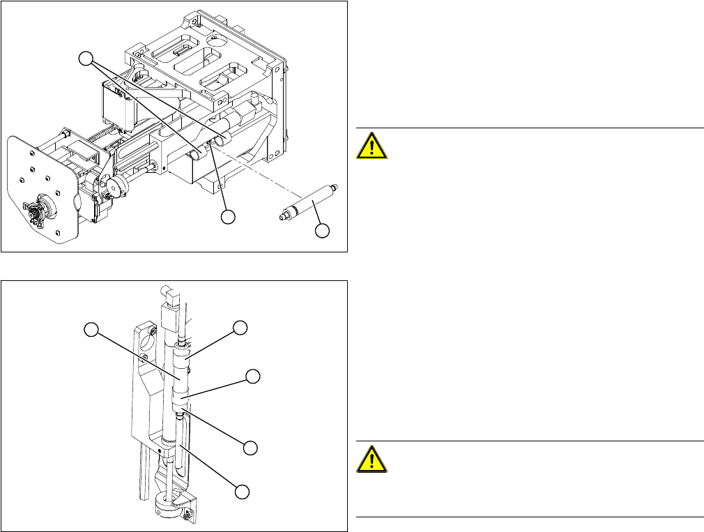
Removal/Installation
► Remove the vacuum hoses on the vacuum control
system and on the rotary axis.
► Loosen the two clips (2) for the additional volume with
air filter (1).
► Loosen the screw fastening the clamping piece (3) for
the clips.
CAUTION! This air filter unit may NOT be used
in combination with the digital vacuum generator. The
volume has been exactly designed for the respective
controller type.
► Fit the additional volume with the air filter (1) facing
downwards, with the clips (2).
► Connect the vacuum hose. Turn the filter so that the
vacuum hose (4) runs in a loop towards the rotary ax-
is.
► Fasten the filter so that the bottom union nut (3) is fit-
ted closely to the clip (2). When moving upwards, the
Z axis must not hit any part of the Twin head .
CAUTION! Kinked vacuum hoses must be re-
placed.
Make sure the vacuum hose is never kinked or jammed.
► Push the Z axis upwards. The rotary axis and the vac-
uum hose must not touch the base.
► Perform a complete installation check. (see "4.5.2.3
Installation Check" [ ➙ 166])
1
3
2
2
4
1
3
2
Service Work
Pick&Place Head 4.5.2 Replacing the Vacuum Control System, Filter and Additional Volume
166 Service Manual SIPLACE D1/D1i/D2/D2i
4.5.2.3
4.5.2.3 Installation Check
Installation Check
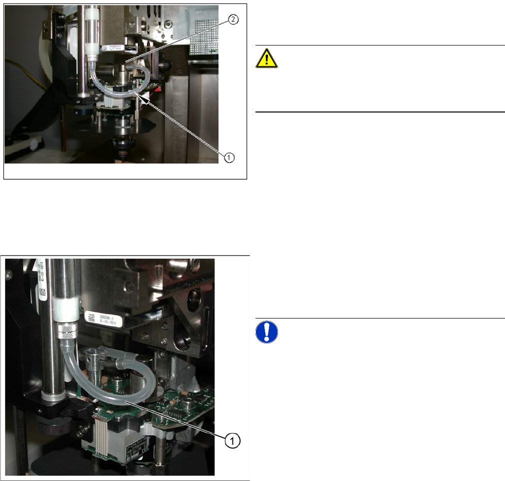
The following steps apply for the rotary axis of the P&P
head, version 14 (without metal elbow for vacuum feed-in
on the DP turning unit):
CAUTION! Check the alignment of the rotary ax-
is!
Check that the rotary axis is always aligned towards the
front.
► This means that the rotary axis must not hit any parts
when in the top Z axis position (2). Check this several
times by moving the Z axis to its minimum and maxi-
mum positions and turning the rotary axis, with the
vacuum hose connected. This should then automati-
cally revert to its original, free-moving position (1).
► Run the SITEST program to calibrate the vacuum
system (calibrate „Vacuum closed“ and „zero correc-
tion for the Pressure regulator“).
Rotary axis for P&P head version 5
Legend
1. Silicon inlet air hose for D axis vacuum air blast
The following steps apply for the rotary axis of the P&P
head, version 5:
NOTICE! The rotary axis does not need to be
aligned for P&P head version 5.
► Run the SITEST program to calibrate the vacuum
system (calibrate „Vacuum closed“ and „zero correc-
tion for the Pressure regulator“).
Service Work
4.5.2 Replacing the Vacuum Control System, Filter and Additional Volume Pick&Place Head
Service Manual SIPLACE D1/D1i/D2/D2i 167
4.5.2.4
4.5.2.4 Replacing the Vacuum Control System (Version 02 - Digital) [03058802-xx]
Replacing the Vacuum Control System (Version 02 - Digital) [03058802-xx]
Removal
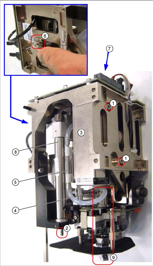
TWIN segment 1 front view / TWIN segment 2 rear view
The digital vacuum generator has a thin high-precision
tube (additional volume tube) in the vacuum supply to the
nozzle. Between this pipe and the vacuum connection of
the vacuum generator, there is an air filter attached to the
TWIN segment.
► Open the threaded pin on the stopper ((2) already re-
moved in the diagram here) of the return unit and un-
screw the stopper.
► Pull the silicon hose (4) off the connecting piece of
the high-precision tube (5).
► Loosen the two clamping screws (6) on the air filter.
► Loosen the two fastening screws (1) on the vacuum
control system (3) and remove the vacuum control
system.
► Pull the vacuum control system downwards so that it
can be unplugged from the head main board (7).
► Unthread the vacuum control system next to the re-
turn cylinder (8) and above the DP turning unit (9) on
the Z mechanics.