00195376-05_SM_D1_D1i_D2_D2i_EN.pdf - 第175页
Service Work 4.5.7 Replacing the Stationary Digital Component/FC Camera [030 20578-xx] Pick&Place Head Service Manual SIPLACE D1/D1i/D2/D2i 175 4.5.7 4 . 5 . 7 R e p la c in g t h e S t a t io n a r y D ig it a l C o…
Service Work
Pick&Place Head 4.5.6 Replacing the Control Cable for the DP Unit - Force Sensor [03005289]
174 Service Manual SIPLACE D1/D1i/D2/D2i
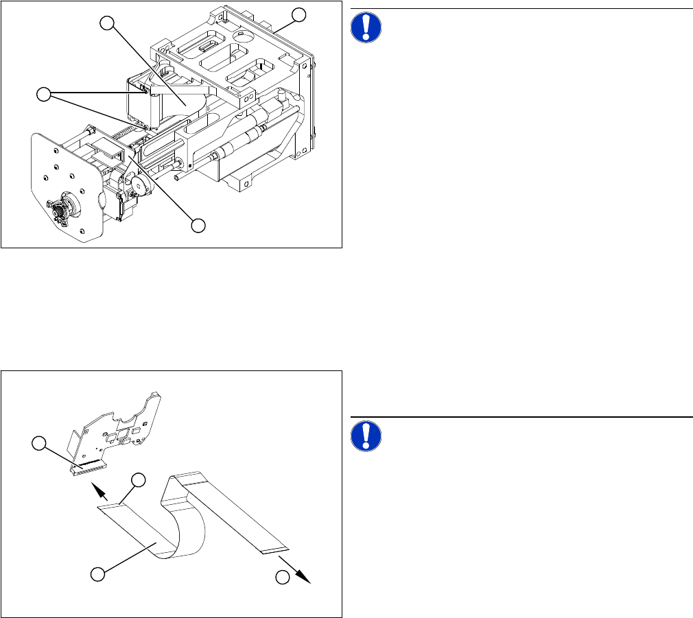
Removal/Installation
NOTICE! Make sure you note the correct con-
tact position of the control cables during removal and in-
stallation. The installation position is marked in blue.
► Disconnect the control cable from the force measur-
ing board (1). To do this, pull the two locking handles
on the plug up and out.
► Loosen the two screws fastening the flat ribbon
mount (2).
⇨ To access the plug, the main head board (3) must
be removed.
► Remove the head main board (3). Take care not to
lose the four spacer sleeves.
► Disconnect the control cable (4) from the main head
board (3) and remove the control cable (4).
► Connect the new control cable to the main head
board (3) and fit the flat ribbon mount (2). Pull the
locking handle upwards.
► Insert the control cable (1) until the contacts (4) fully
engage.
NOTICE! Observe the original installation posi-
tion of the control cable.
► Push the two locking handles down. The control ca-
ble should now sit firmly on the plug (2) of the force
measurement board.
⇨ (3) To the main head board.
1
4
3
2
1
4
3
2
Service Work
4.5.7 Replacing the Stationary Digital Component/FC Camera [03020578-xx] Pick&Place Head
Service Manual SIPLACE D1/D1i/D2/D2i 175
4.5.7
4.5.7 Replacing the Stationary Digital Component/FC Camera [03020578-xx]
Replacing the Stationary Digital Component/FC Camera [03020578-xx]
Overview
Removal/Installation
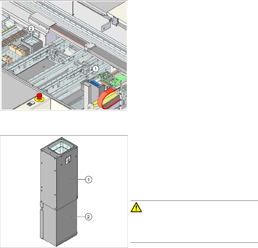
Legend
1. Stationary component camera type 36 (type 33 can
also be fitted as an option)
2. FlipChip camera - stationary type 25 (FC camera)
Item numbers
▪ Stationary component camera P&P (type 36) 55x45
digital [03042491-xx]
▪ Stationary FC camera P&P (type 25) 16x16 digital
[03020578-xx]
► Move the component trolley out of the machine.
► Switch off the machine.
► Carefully lift the upper section (1) of the camera up
and out.
► If possible, avoid touching the camera lens system.
► Remove the camera cover (2).
► Unplug the electrical connections (CAN Bus cable,
Hotlink cable, voltage supply).
CAUTION! Component camera type 25
The four fastening screws holding the component cam-
era type 25 also hold the supporting plate of the camera
calibration point.
Make sure that the supporting plate does not drop down.
► First loosen the two upper fixture screws and replace
these two M6x35 screws with setting screws M6x50
[3005958-xx].
This fixes the "Caul for mark" in place.
► Now loosen the other two M6x50 fastening the base
plate of the stationary camera.
Service Work
Pick&Place Head 4.5.8 Replacing the Servo Amplifier [00353446]
176 Service Manual SIPLACE D1/D1i/D2/D2i
Installation
4.5.8
4.5.8 Replacing the Servo Amplifier [00353446]
Replacing the Servo Amplifier [00353446]
See also
4.1.5 Replacing the Servo Card [ ➙ 58]
4.5.9
4.5.9 Replacing the Air Filter
Replacing the Air Filter
4.5.9.1
4.5.9.1 Replacing the Air Filter (Analog Vacuum Control System) [03051420-xx]
Replacing the Air Filter (Analog Vacuum Control System) [03051420-xx]
► Fit the new camera module and fasten it with the 4
screws (together with the supporting plate of the cam-
era calibration point, where necessary).
► Reconnect to the electricity system.
► Check the DIP switch on the camera. (See "6.6.2 DIP
Switch for Camera Types 25, 33 and 36" [ ➙ 245].)
► Fit the lower cover (2) onto the component camera.
► Carefully place the upper part (1) onto the camera
module.
► Calibrate the component camera with the SITEST
program.
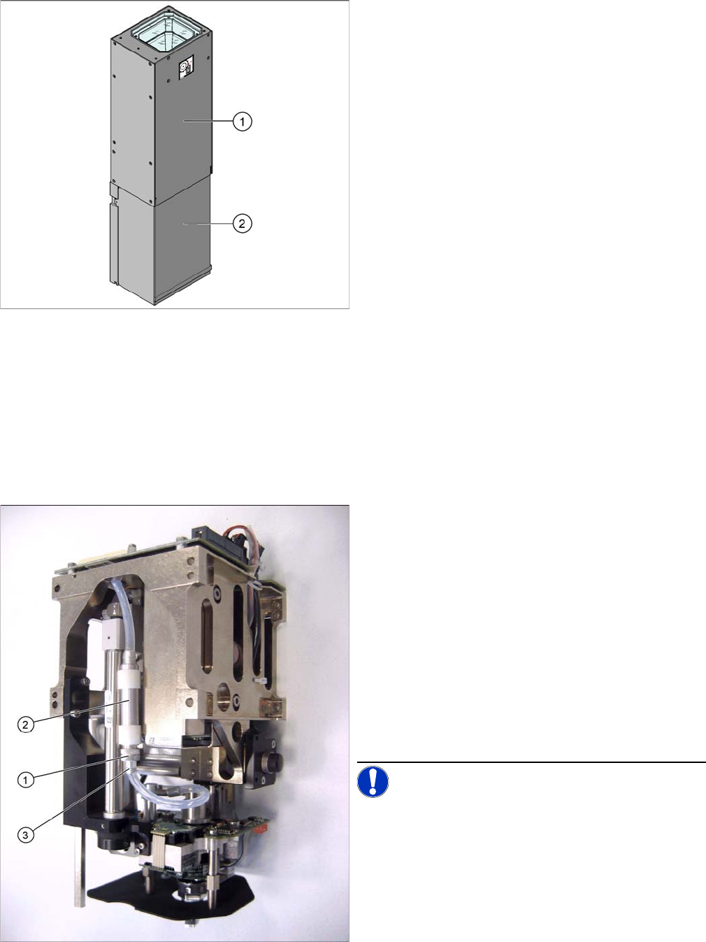
TWIN segment 1 front view / TWIN segment 2 rear view
The analog vacuum generator has a thin high-precision
tube (additional volume tube) in the vacuum supply to the
nozzle. At the bottom screwed connection on this Rohr
you will find the air filter which protects the vacuum gen-
erator from contaminants introduced via the nozzle.
► Open the screwed connection pointing downwards
(1) on the additional volume (filter assembly) (2) and
pull off the connection piece with the silicon hose (3).
► The filter can now be removed via the open hole (use
tweezers). The filter cageis open at the bottom to ac-
commodate the suction contaminants.
► Clean or replace the filter.
► Refit and fasten the connection piece back into place.
NOTICE! This air filter unit may NOT be used in
combination with the digital vacuum generator. The vol-
ume has been exactly designed for the respective con-
troller type.