00195376-05_SM_D1_D1i_D2_D2i_EN.pdf - 第181页
Service Work 4.6.4 Replacing the Communication U nit (Feeder Control Unit) [0 3002179-xx] Changeover Table Service Manual SIPLACE D1/D1i/D2/D2i 181 4.6.4 4 . 6 . 4 R e p la c in g t h e C o m m u n ic a t io n U n it ( F…
Service Work
Changeover Table 4.6.3 Replacing the Fixed and/or Guide Castors
180 Service Manual SIPLACE D1/D1i/D2/D2i
See also
4.6.1 Safety Instructions [ ➙ 178]
3.8.1 Parts Overview [ ➙ 43]
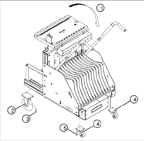
Replacing the fixed and guide castors (D4 shown as ex
-
ample)
Legend
1. Lay the changeover table on its side (2nd person re-
quired) before removing the rollers.
2. Fixed castors (2 units)
3. 8 hexagon socket-head screws M8 x 16
4. Double guide castors (2 units)
5. 8 hexagon socket-head screws M8 x 16
Service Work
4.6.4 Replacing the Communication Unit (Feeder Control Unit) [03002179-xx] Changeover Table
Service Manual SIPLACE D1/D1i/D2/D2i 181
4.6.4
4.6.4 Replacing the Communication Unit (Feeder Control Unit) [03002179-xx]
Replacing the Communication Unit (Feeder Control Unit) [03002179-xx]
See also
4.6.6 Final Steps [ ➙ 182]
4.6.5
4.6.5 Replacing the Changeover Table Connection Cable
Replacing the Changeover Table Connection Cable
Power supply cable "changeover table"
► Perform the "Preparatory Steps". (See "4.6.2 Preparations for Service Work" [ ➙ 179].)
You do not need to dismantle the feeder modules.
► Unplug plugs X13 and X15 of the communication unit cable.
► Disconnect the pneumatic hose.
► Disconnect the ground cable at the connection provided.
► The ground cable is looped through the changeover table and fastened at several connections.
To avoid weaving out the complete ground cable, disconnect the cable at the cable shoe.
► Open the cord grip and remove the entire cable.
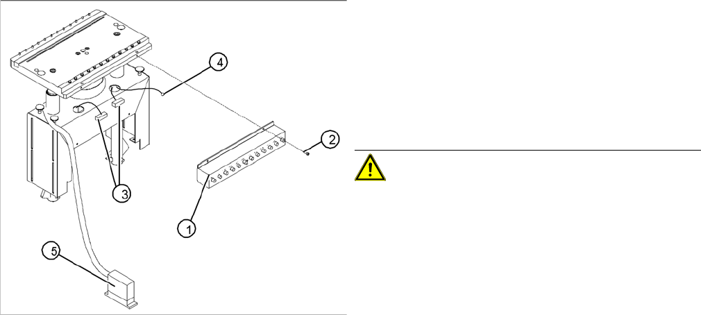
Replacing the communications unit; view of the change
-
over table connection area (D4 shown as example)
Legend
1. Communication unit (Feeder Control Unit)
2. Fasteners for the communications unit: 2 M 4 x 6 hex-
agon socket-head screws
3. "Changeover table" connection cable
4. Ground cable with cable shoe
5. "Changeover table" connection cable - connector
CAUTION! The same fastening screws can be
used to fit a splice detection unit. Bear this in mind when
loosening the screws.
► Perform the "Preparatory Steps" (see "4.6.2 Prepara-
tions for Service Work" [ ➙ 179]).
You do not need to dismantle the feeder modules.
► Unplug the two press-fit connections for the "change-
over table“ cable, at the back of the communication
unit housing (3) and remove the ground cable (4).
► Hold the communication unit and undo the fastening
screws (2).
► Remove the communication unit (1).
► Place the new communications unit on the retaining
brackets and tighten the screws to fasten it.
► Reconnect the "changeover table" cable at the back
of the communications unit housing.
► If you have no further parts to be exchanged, perform
the appropriate "Final Steps", including a table func-
tion check with SITEST.
Service Work
Changeover Table 4.6.6 Final Steps
182 Service Manual SIPLACE D1/D1i/D2/D2i
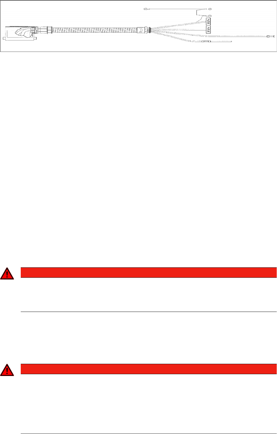
Cable for changeover table (D4 shown as example)
► Feed the new cable into the cord grip from the top to the bottom.
► Plug in the communication unit connection cable and reconnect the pneumatic system.
► Run the cable and attach cable ties.
► If you have no further parts to be exchanged, perform the appropriate "Final Steps", including a table
function check with SITEST.
See also
4.6.6 Final Steps [ ➙ 182]
4.6.6
4.6.6 Final Steps
Final Steps
► Check the contact surface for the feeder modules on the changeover table:
If necessary, clean the surface, as described in the User Manual in chapter "Maintenance".
► Place the feeder modules incl. the tape reels in the right order on the changeover table (in accord-
ance with the specifications for setup optimization).
If an external setup location is available, perform the setup there, incl. inserting the tapes and check-
ing the allocations „Feeder module / track“ and „Component/ track“.
► Connect all feeder modules to the relevant jack of the communications unit (changeover table termi-
nation panel).
► Switch the machine on. The compressed air is attached. Move the changeover table back into the
machine and connect it. To do this, plug in the changeover table and lower it onto the changeover
table rest and centering point.
Perform the steps in the correct order!
► Make sure that the changeover table has been correctly inserted into the machine!
► Reconnect to the power supply supply.
► If this has not been done yet, insert the tapes now and check the allocation of feeder module and
component (component bar code scanner).
► Step / transport the first component into the pickup position. VISUALLY CHECK the front of the mod-
ule to see if all tapes move smoothly into the empty-tape duct.
DANGER
Guard (dummy module)
The changeover table, which has been moved into the machine, must always be completely
equipped with feeder modules or dummy modules (see User Manual and Service Manual,
chapters " "Operational Safety").
DANGER
The SITEST program may only be started by personnel who have been trained in its use by
Siemens and are therefore authorized to do so.
► The cutter must also be completely assembled for work with the SITEST program. The
changeover table must be moved into the machine and docked correctly.
► The changeover table, which has been moved into the machine, must always be completely
equipped with feeder modules or dummy modules (see User Manual and Service Manual,
chapters " "Operational Safety").