00195376-05_SM_D1_D1i_D2_D2i_EN.pdf - 第184页
Service Work Cutter 4.8.1 Replacing the Cutter [03041 953] 184 Service Manual SIPLACE D1/D1i/D2/D2i 4.8 4 . 8 C u t t e r Cutter 4.8.1 4 . 8 . 1 R e p la c in g t h e C u t t e r [ 0 3 0 4 1 9 5 3 ] Replacing the Cu tter…
Service Work
4.7.1 Pneumatic Unit Manometer [03043756] Pneumatic Unit
Service Manual SIPLACE D1/D1i/D2/D2i 183
► After exchanging the cable for the changeover table and/or the communications unit:
Note the DANGER text regarding the SITEST program.
Load the SITEST program and check the changeover table functions.
► Exit the SITEST program.
► Start the placement process.
4.7
4.7 Pneumatic Unit
Pneumatic Unit
4.7.1
4.7.1 Pneumatic Unit Manometer [03043756]
Pneumatic Unit Manometer [03043756]
Supply pressure
CAUTION
Prolonged interruptions to the compressed air supply can cause damage.
When the machine is switched on, do not use the stop valve to interrupt the compressed air
supply for more than 30 minutes. If you need to shut off the compressed air system for longer
in order to carry out maintenance or servicing work, you must switch the placement system off
at the main switch and disconnect it from the power supply.
CAUTION
Risk of injury from compressed air!
NEVER disconnect compressed air lines while they are still pressurized. Risk of injury!
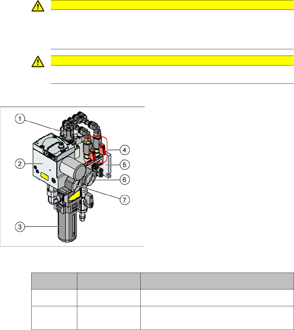
Legend
1. Pressure regulator for setting the bulkcase feeder
pressure
2. Centronic flange
3. Compressed air filter
4. Pressure shutoff taps for gantry(ies)
5. Fixtures for pneumatic unit
6. Manometer – bulkcase conveyor
7. Manometer – regulated pressure
Manometer /
Pos. No.
Target pressure Description
(6) 2.5 bar (+/- 0.5 bar)
(manually set)
(For bulkcase, nozzle changers C&P6/12)
(7) 5.1 (+/- 0.1 bar)
(electronically regulat-
ed)
For tape cutters, conveyors, changeover tables
For gantries (vacuum for C&P head and Twin head)
Service Work
Cutter 4.8.1 Replacing the Cutter [03041953]
184 Service Manual SIPLACE D1/D1i/D2/D2i
4.8
4.8 Cutter
Cutter
4.8.1
4.8.1 Replacing the Cutter [03041953]
Replacing the Cutter [03041953]
Removal/Installation
4.8.2
4.8.2 Replacing the Articulated Joint on the Short-Stroke Cylinder [03000518-xx]
Replacing the Articulated Joint on the Short-Stroke Cylinder [03000518-xx]
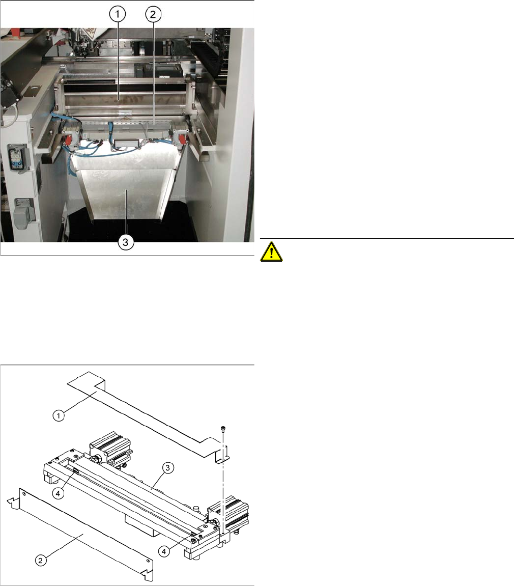
Removal
► Move the relevant component trolley out of the ma-
chine.
► Switch off the machine.
► Dismantle the bumper for the changeover table (2 x
screws each on left and right).
► Dismantle the empty tape duct (1). To do this, loosen
the 4 fitting screws for the empty tape duct, from
above.
► Dismantle the waste slide (3). To do this, loosen the
4 corresponding fitting screws, from below.
► Disconnect or unscrew all leads to the tape cutter (3)
(CAN, 2x compressed air, voltage supply). Open the
cable duct to do this.
► Loosen the 4 fitting screws for the tape cutter, from
below.
► Lift the tape cutter upwards and out.
CAUTION! Heavy machine part!
► To fit the tape cutter again, follow the above instruc-
tions in the reverse order.
► Dismantle the empty tape duct.
► Dismantle the component trolley feed device, the two
bumpers for the component trolley (on the left and
right) and the cutter.
► Loosen the cover plate (2).
► Open the cable duct (3) and remove all cables.
► Remove the cover plate (1).
► Remove the caps (4) on the fastening screws.
Service Work
4.8.2 Replacing the Articulated Joint on the Short-Stroke Cylinder [03000518-xx] Cutter
Service Manual SIPLACE D1/D1i/D2/D2i 185
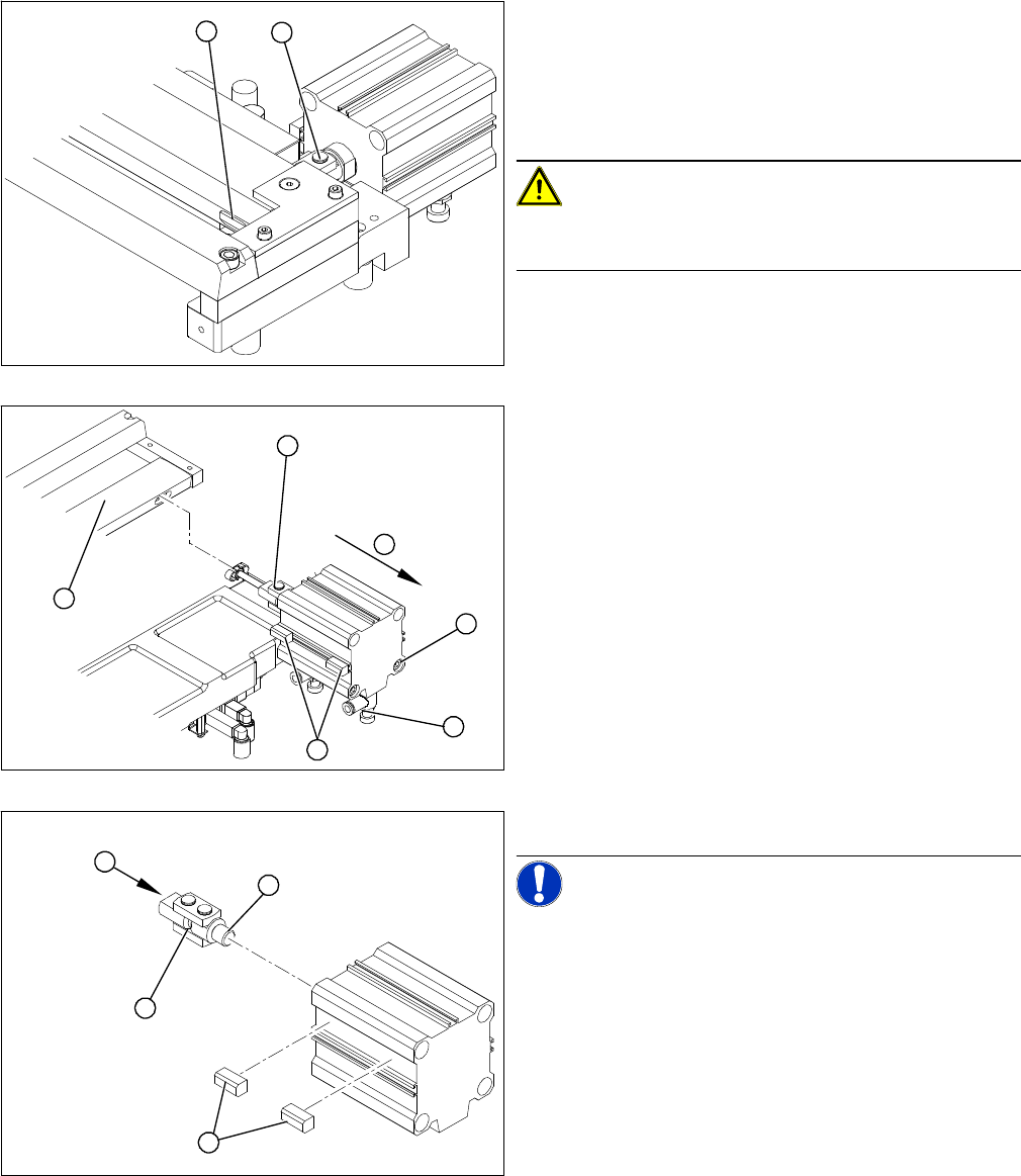
Legend
1. Articulated joint on the short-stroke cylinder
2. Fastening screw on the moveable blade (under the
cover flap)
► Loosen the screw (2) holding the moveable blade.
CAUTION! Risk of injury!
There is a risk of injuring yourself on the cutting edges of
the blades.
► Use a permanent marker to mark the exact installa-
tion position of the proximity switch (1) on the short-
stroke cylinder. Mark the hoses.
► Loosen the screws fastening the two inductive prox-
imity switches (1) to the short-stroke cylinder.
► Remove the compressed air connections (2) on the
short-stroke cylinder.
► Remove the two screws (3) holding the short-stroke
cylinder.
► Pull the short-stroke cylinder (4) and the articulated
joint screwed into it (5) out of the cutter set (6).
► Unscrew the articulated joint (1) from the cylinder.
NOTICE! The threaded pin is secured with Loc-
tite no 241. You will need somewhat more strength than
usual to loosen it.
► Apply a small amount of Loctite no. 241 to the thread
(2) of the new joint.
► Screw the articulated joint (1) into the short-stroke
cylinder.
► Turn the articulated joint into the installation position
(3). Once the cylinder is installed, the slot in the
moveable blade prevents the articulated joint from
turning.
1
2
1
6
5
4
3
2
1
4
3
2