00195376-05_SM_D1_D1i_D2_D2i_EN.pdf - 第185页
Service Work 4.8.2 Replacing the Articulated Joint on the Short-Stroke C ylin der [03000518-xx] Cutter Service Manual SIPLACE D1/D1i/D2/D2i 185 Legend 1. Articulated joint on th e short-stroke c ylinder 2. Fastening scre…
Service Work
Cutter 4.8.1 Replacing the Cutter [03041953]
184 Service Manual SIPLACE D1/D1i/D2/D2i
4.8
4.8 Cutter
Cutter
4.8.1
4.8.1 Replacing the Cutter [03041953]
Replacing the Cutter [03041953]
Removal/Installation
4.8.2
4.8.2 Replacing the Articulated Joint on the Short-Stroke Cylinder [03000518-xx]
Replacing the Articulated Joint on the Short-Stroke Cylinder [03000518-xx]
Removal
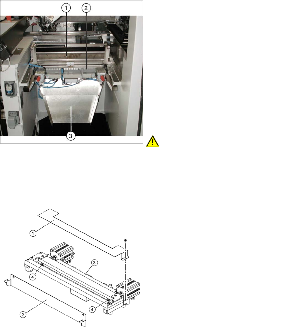
► Move the relevant component trolley out of the ma-
chine.
► Switch off the machine.
► Dismantle the bumper for the changeover table (2 x
screws each on left and right).
► Dismantle the empty tape duct (1). To do this, loosen
the 4 fitting screws for the empty tape duct, from
above.
► Dismantle the waste slide (3). To do this, loosen the
4 corresponding fitting screws, from below.
► Disconnect or unscrew all leads to the tape cutter (3)
(CAN, 2x compressed air, voltage supply). Open the
cable duct to do this.
► Loosen the 4 fitting screws for the tape cutter, from
below.
► Lift the tape cutter upwards and out.
CAUTION! Heavy machine part!
► To fit the tape cutter again, follow the above instruc-
tions in the reverse order.
► Dismantle the empty tape duct.
► Dismantle the component trolley feed device, the two
bumpers for the component trolley (on the left and
right) and the cutter.
► Loosen the cover plate (2).
► Open the cable duct (3) and remove all cables.
► Remove the cover plate (1).
► Remove the caps (4) on the fastening screws.
Service Work
4.8.2 Replacing the Articulated Joint on the Short-Stroke Cylinder [03000518-xx] Cutter
Service Manual SIPLACE D1/D1i/D2/D2i 185
Legend
1. Articulated joint on the short-stroke cylinder
2. Fastening screw on the moveable blade (under the
cover flap)
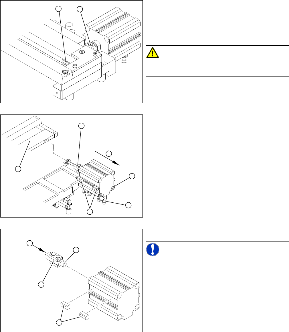
► Loosen the screw (2) holding the moveable blade.
CAUTION! Risk of injury!
There is a risk of injuring yourself on the cutting edges of
the blades.
► Use a permanent marker to mark the exact installa-
tion position of the proximity switch (1) on the short-
stroke cylinder. Mark the hoses.
► Loosen the screws fastening the two inductive prox-
imity switches (1) to the short-stroke cylinder.
► Remove the compressed air connections (2) on the
short-stroke cylinder.
► Remove the two screws (3) holding the short-stroke
cylinder.
► Pull the short-stroke cylinder (4) and the articulated
joint screwed into it (5) out of the cutter set (6).
► Unscrew the articulated joint (1) from the cylinder.
NOTICE! The threaded pin is secured with Loc-
tite no 241. You will need somewhat more strength than
usual to loosen it.
► Apply a small amount of Loctite no. 241 to the thread
(2) of the new joint.
► Screw the articulated joint (1) into the short-stroke
cylinder.
► Turn the articulated joint into the installation position
(3). Once the cylinder is installed, the slot in the
moveable blade prevents the articulated joint from
turning.
1
2
1
6
5
4
3
2
1
4
3
2
Service Work
Cutter 4.8.3 Replacing the Control Unit [03006411]
186 Service Manual SIPLACE D1/D1i/D2/D2i
Installation
4.8.3
4.8.3 Replacing the Control Unit [03006411]
Replacing the Control Unit [03006411]
Removal/Installation
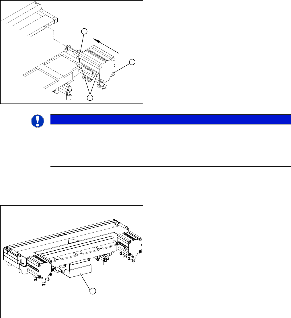
► Install the proximity switch (1) precisely in the position
you marked with the permanent marker.
► Insert the prepared cylinder into the cutter, with the
correct rotary position of the articulated joint (2) i.e.
the joint axes must be vertical.
► Fasten the cylinder in this position, with the 2 screws
provided (3).
► Connect the compressed air hoses to the cylinder in
the correct allocation.
► Check the gap between the leading edge of the tape
deflector and the "empty-tape baffle, inside".
► Check the switching points of the proximity switches.
1
3
2
NOTICE
If the tapes are not cut correctly, even though the switching points have been set properly and
the short-stroke cylinder has been exchanged - complete with the one-way restrictor - the cause
of the problem may be:
► Incorrect compressed air level
► Leaking compressed air connection or Y-socket union
Legend
1. Control unit under the cover
► Dismantle the waste slide.
► Remove the cover (1) from the control unit.
1