00195376-05_SM_D1_D1i_D2_D2i_EN.pdf - 第188页
Service Work Cutter 4.8.5 Replacing the Proximity Switch [00332894] 188 Service Manual SIPLACE D1/D1i/D2/D2i Removal/Installation 4.8.5 4 . 8 . 5 R e p la c in g t h e P r o x im it y S w it c h [ 0 0 3 3 2 8 9 4 ] Repla…
Service Work
4.8.4 Replacing the Solenoid Valves [03000630] Cutter
Service Manual SIPLACE D1/D1i/D2/D2i 187
4.8.4
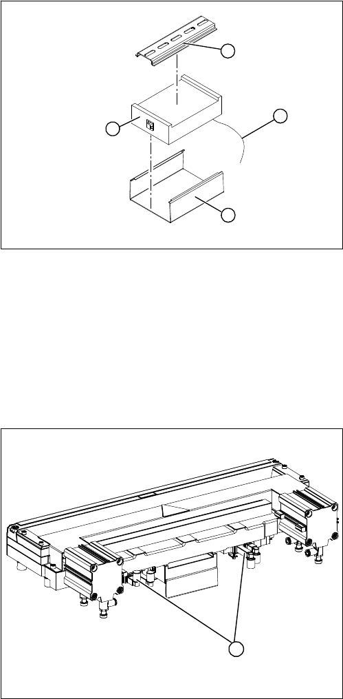
4.8.4 Replacing the Solenoid Valves [03000630]
Replacing the Solenoid Valves [03000630]
Overview
► Mark the allocation of all press-fit connections and
disconnect all press-fit connections (2) from the con-
trol unit.
► Remove the cable ties and the connection cable fix-
tures.
► Carefully pull the control unit (3) off its mount (4).
► Carefully insert the new control unit onto the mount,
in the correct rotary position and location, until it locks
into place.
► Restore all plug-and socket connections in the cor-
rect allocation.
► Run the connection cables and fasten with cable ties
(strain relief).
► Check the jumper setting according to the label on
the control unit and adjust, if necessary.
► Replace the control unit cover.
► Fit the waste slide.
1
4
3
2
1. Position of the solenoid valves
1
Service Work
Cutter 4.8.5 Replacing the Proximity Switch [00332894]
188 Service Manual SIPLACE D1/D1i/D2/D2i
Removal/Installation
4.8.5
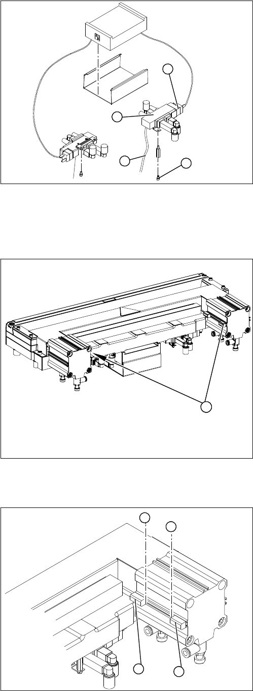
4.8.5 Replacing the Proximity Switch [00332894]
Replacing the Proximity Switch [00332894]
Overview
Removal/Installation
Legend
1. Solenoid valve assembly
► Loosen the compressed air connections (3) on the
solenoid valve.
► Unplug the press-fit connection (2) on the solenoid
valve connection cable.
► Loosen the screws (4) holding the solenoid valve in
place and remove the solenoid valve.
► Fit the new solenoid valve and establish the press-fit
connection to the valve.
Attach cable ties (strain relief) where necessary.
1
4
3
2
Legend
1. 2 proximity switches on each short-stroke cylinder
1
► Use a permanent marker to mark the exact installa-
tion position (3) of the proximity switch (1) or (2) on
the short-stroke cylinder.
► Loosen the screw fastening the proximity switch to
the short-stroke cylinder.
► Unthread the connection cable to the control unit.
► Install the proximity switch precisely in the position (3)
you marked with the permanent marker on the short-
stroke cylinder.
► Secure the fastening screws with locking varnish.
► Reconnect to the electricity supply.
► Check the switching points of the proximity switches.
1
2
3
3
Service Work
4.8.6 Replacing the Cutter Blades [03009259-xx] Cutter
Service Manual SIPLACE D1/D1i/D2/D2i 189
4.8.6
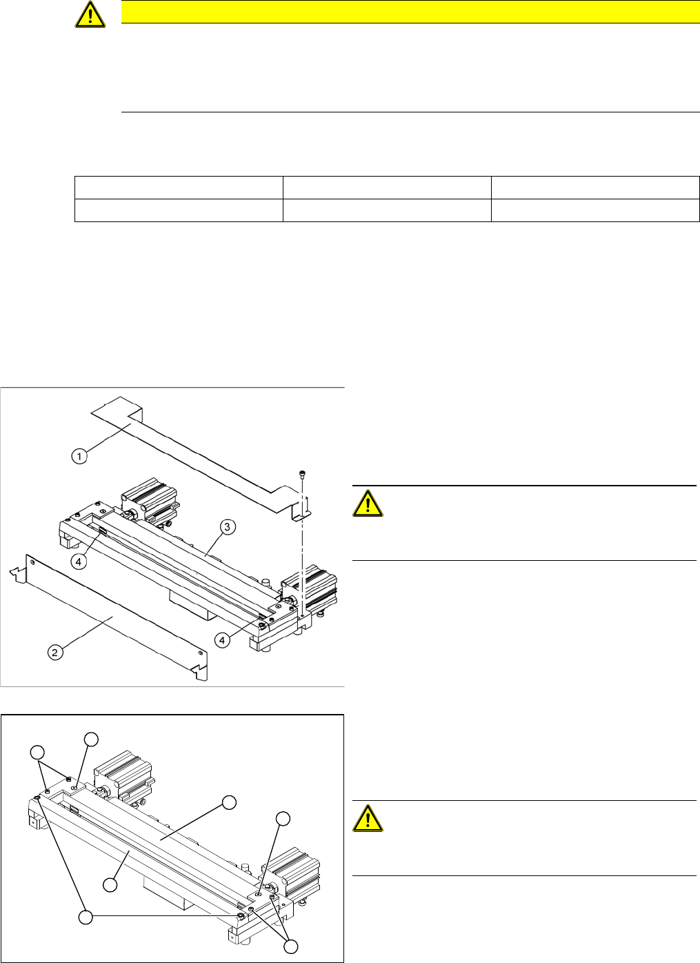
4.8.6 Replacing the Cutter Blades [03009259-xx]
Replacing the Cutter Blades [03009259-xx]
Parts
The article number of the cutter blades may vary according to the cutter version and function status.
Tools and equipment
▪ Thick protective gloves
▪ Assembly plate [00312731-xx]
Alternatively: 2 large parallel clamps and a sturdy table with even surface, to clamp down the dis-
mantled cutter
Removal
CAUTION
Risk of injury!
There is a high risk of injury from the blades and the tape deflector.
► Wear appropriately thick protective gloves!
► Never reach into the cutter from below or into the empty-tape duct from above.
Tape cutter, pneumatic Function status Cutter blades, attuned
03019941 -03 03009259-xx
► Dismantle the empty tape duct and remove the cutter.
► Loosen the cover plate (2).
► Remove the cover plate (1).
► Remove the caps (4) on the fastening screws.
CAUTION! Risk of injury!
There is a risk of injuring yourself on the cutting edges of
the blades.
► For all further work, either fix the cutter to the mount-
ing plate with 4 hexagon socket-head screws or use
screw clamps to fasten the cutter to a sturdy table.
► Loosen and remove the two screws (1) fastening the
stationary blade (2).
► Loosen the screws fastening the left and right tape
deflectors (3) above the moveable blade.
CAUTION! Do not loosen all screws!
Do not loosen the two countersunk socket-head screws
(4)
► Remove the tape deflector holder with the tape de-
flector (5) and carefully place the whole unit down
(with the tape deflector facing upwards).
4
3
5
1
4
3
2