00195376-05_SM_D1_D1i_D2_D2i_EN.pdf - 第189页
Service Work 4.8.6 Replacing the Cutter Blades [03009259-xx] Cutter Service Manual SIPLACE D1/D1i/D2/D2i 189 4.8.6 4 . 8 . 6 R e p la c in g t h e C u t t e r B la d e s [ 0 3 0 0 9 2 5 9 - x x ] Replacing the Cutter Bla…
Service Work
Cutter 4.8.5 Replacing the Proximity Switch [00332894]
188 Service Manual SIPLACE D1/D1i/D2/D2i
Removal/Installation
4.8.5
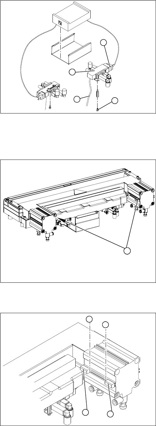
4.8.5 Replacing the Proximity Switch [00332894]
Replacing the Proximity Switch [00332894]
Overview
Removal/Installation
Legend
1. Solenoid valve assembly
► Loosen the compressed air connections (3) on the
solenoid valve.
► Unplug the press-fit connection (2) on the solenoid
valve connection cable.
► Loosen the screws (4) holding the solenoid valve in
place and remove the solenoid valve.
► Fit the new solenoid valve and establish the press-fit
connection to the valve.
Attach cable ties (strain relief) where necessary.
1
4
3
2
Legend
1. 2 proximity switches on each short-stroke cylinder
1
► Use a permanent marker to mark the exact installa-
tion position (3) of the proximity switch (1) or (2) on
the short-stroke cylinder.
► Loosen the screw fastening the proximity switch to
the short-stroke cylinder.
► Unthread the connection cable to the control unit.
► Install the proximity switch precisely in the position (3)
you marked with the permanent marker on the short-
stroke cylinder.
► Secure the fastening screws with locking varnish.
► Reconnect to the electricity supply.
► Check the switching points of the proximity switches.
1
2
3
3
Service Work
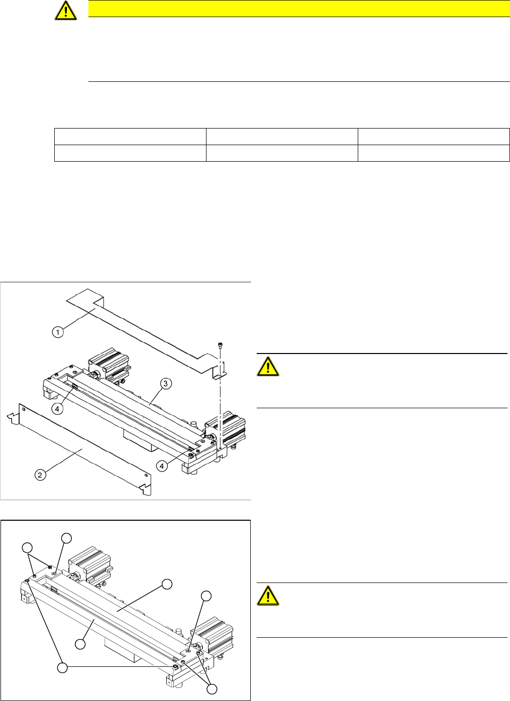
4.8.6 Replacing the Cutter Blades [03009259-xx] Cutter
Service Manual SIPLACE D1/D1i/D2/D2i 189
4.8.6
4.8.6 Replacing the Cutter Blades [03009259-xx]
Replacing the Cutter Blades [03009259-xx]
Parts
The article number of the cutter blades may vary according to the cutter version and function status.
Tools and equipment
▪ Thick protective gloves
▪ Assembly plate [00312731-xx]
Alternatively: 2 large parallel clamps and a sturdy table with even surface, to clamp down the dis-
mantled cutter
Removal
CAUTION
Risk of injury!
There is a high risk of injury from the blades and the tape deflector.
► Wear appropriately thick protective gloves!
► Never reach into the cutter from below or into the empty-tape duct from above.
Tape cutter, pneumatic Function status Cutter blades, attuned
03019941 -03 03009259-xx
► Dismantle the empty tape duct and remove the cutter.
► Loosen the cover plate (2).
► Remove the cover plate (1).
► Remove the caps (4) on the fastening screws.
CAUTION! Risk of injury!
There is a risk of injuring yourself on the cutting edges of
the blades.
► For all further work, either fix the cutter to the mount-
ing plate with 4 hexagon socket-head screws or use
screw clamps to fasten the cutter to a sturdy table.
► Loosen and remove the two screws (1) fastening the
stationary blade (2).
► Loosen the screws fastening the left and right tape
deflectors (3) above the moveable blade.
CAUTION! Do not loosen all screws!
Do not loosen the two countersunk socket-head screws
(4)
► Remove the tape deflector holder with the tape de-
flector (5) and carefully place the whole unit down
(with the tape deflector facing upwards).
4
3
5
1
4
3
2
Service Work
Cutter 4.8.6 Replacing the Cutter Blades [03009259-xx]
190 Service Manual SIPLACE D1/D1i/D2/D2i
Installation – requirements
▪ Wear appropriately thick protective gloves!
▪ Make sure all parts are clean before installing them.
▪ The new blades are covered with a fine lubrication film. Do not use fat dissolving agents on the
blades (risk of rust film forming) or apply any additional lubrication (risk of contamination by particles
sticking to the blades). This would only impair the movement of the moveable blade.
▪ If the new blades are not clean, carefully rub them (wear protective gloves) with a well folded, clean
and dry cloth. Do not use fat dissolving agents!
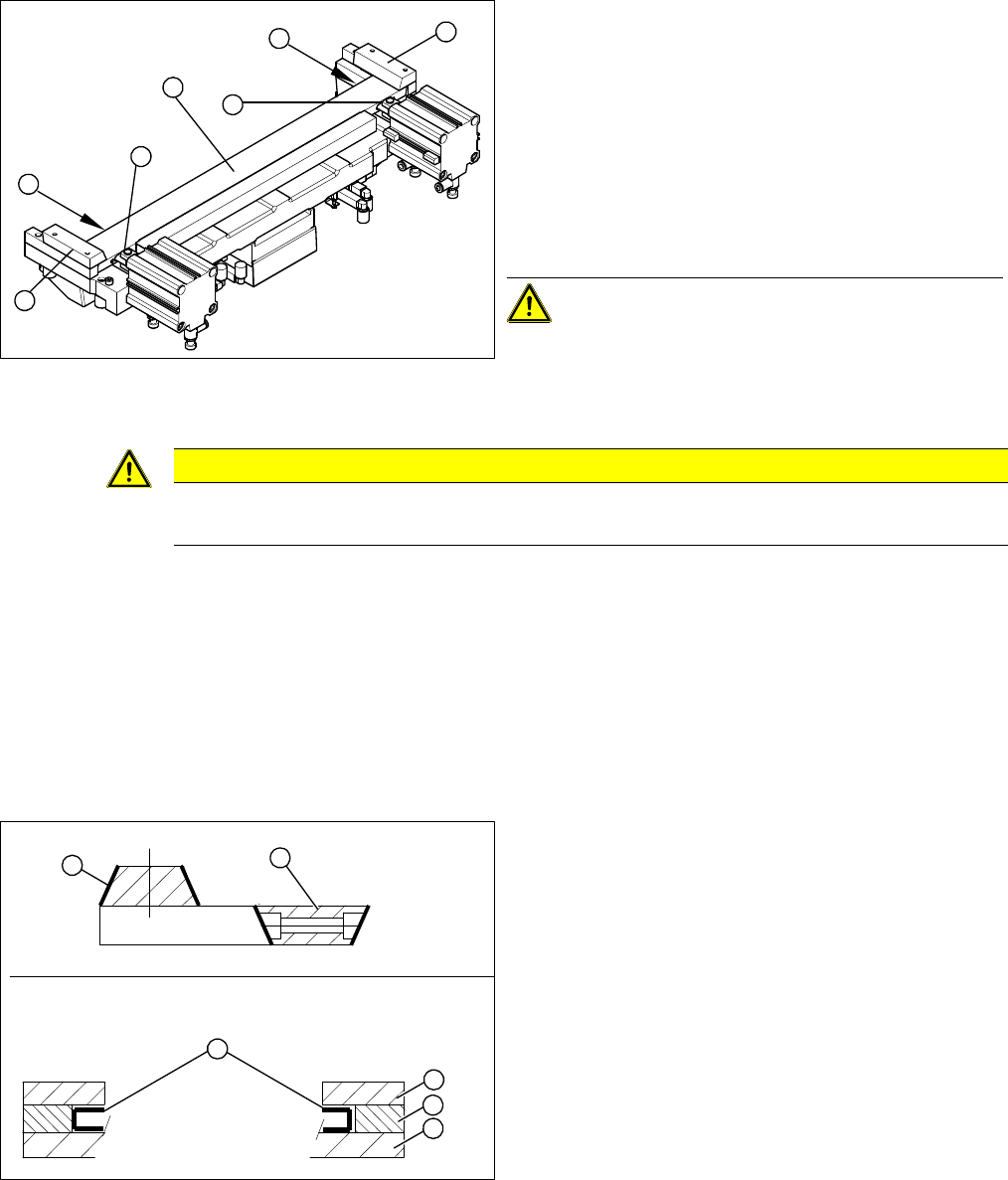
Preparation
► Remove the right-hand holding-down device (1) and
the left holding-down device (2), plus the spacers be-
low.
► Use an SW 14 open-ended wrench to push against
the joint (3), while loosening the hexagon socket-
head screw of the joint (4) in the moveable blade.
This may require more strength than usual as the
screws have been secured with Loctite no. 243.
► Grasp both ends of the moveable blade (5) with the
protective gloves and pull it upwards and out.
CAUTION! Spacers and blades are supplied to
match and may only be replaced together.
3
4
1
5
4
3
2
CAUTION
Risk of injury!
There is a high risk of injury from the blades and the tape deflector.
Legend
1. Stationary blade
2. Moveable blade
3. Sliding surfaces to be lubricated
4. Holding-down device
5. Spacer
6. Contact surface
► Make sure the cutter is in the correct rotary position
(see the slant of the blade).
► Check the positioning of the individual blades to one
another.
► Before installation, lubricate the sliding surface of the
moveable blade.
1
6
5
4
3
2