00195376-05_SM_D1_D1i_D2_D2i_EN.pdf - 第192页
Service Work Cutter 4.8.6 Replacing the Cutter Blades [0 3009259-xx] 192 Service Manual SIPLACE D1/D1i/D2/D2i Final work ► Reinsert the tape deflector unit (3) and screw in the 4 hexagon socket-head screws (4 ) by hand. …
Service Work
4.8.6 Replacing the Cutter Blades [03009259-xx] Cutter
Service Manual SIPLACE D1/D1i/D2/D2i 191
Installation
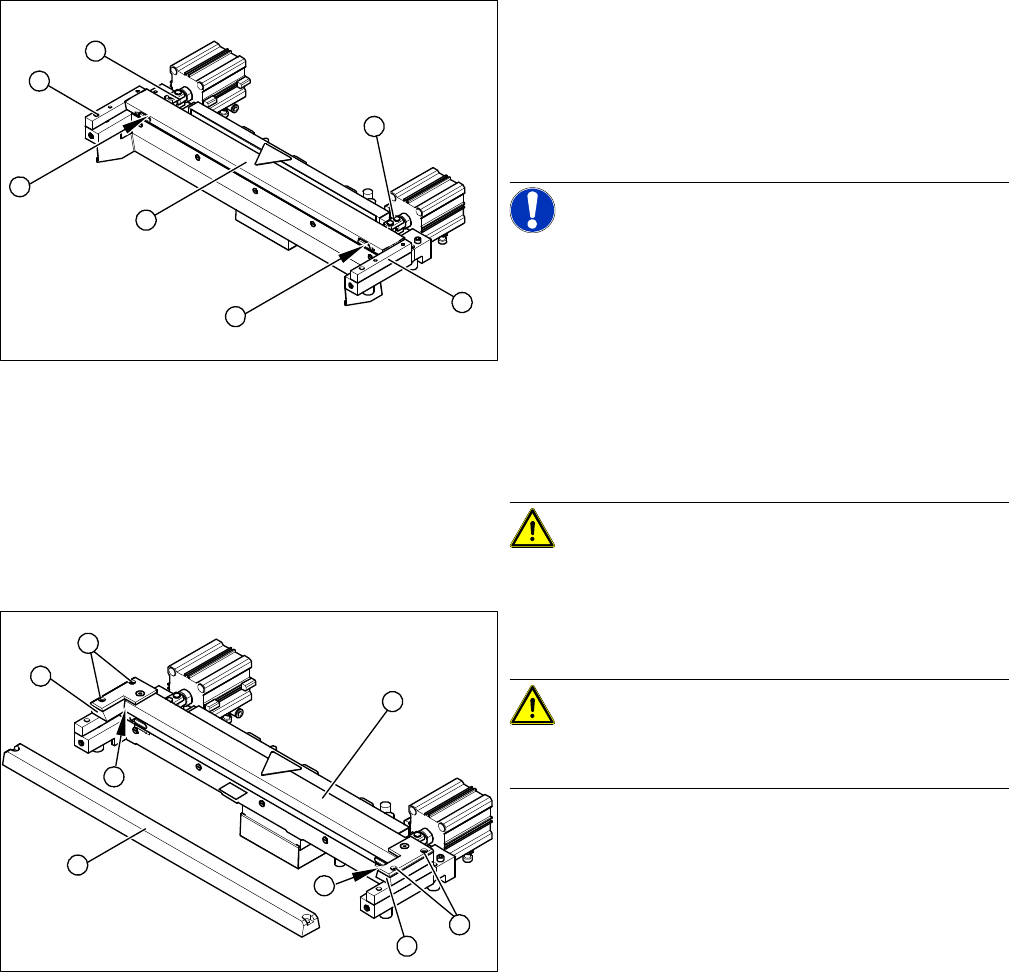
► Correctly insert the moveable blade (1) into the cutter
and shift it along to its original installation position.
► Apply Loctite no. 243 to the two M4 screws, to fasten
the joint in the moveable blade.
► Insert the screws (2) into the left and right holes, pro-
vided in the moveable blade.
NOTICE! Make sure that the joint (3) can slide
into the slot (= anti-twist function) in the moveable blade
without obstruction.
► Use an SW 14 open-ended wrench to push against
the relevant joint (3) and then tighten both screws (2)
to a torque of 2.7. – 3.0. N.
► Replace the two covers (caps).
► Place the two new spacers (4) to the left and right of
the moveable blade. The spacer side marked with a
number must face towards the blade.
CAUTION! Spacers and blades are supplied to
match and may only be replaced together.
► Lubricate the contact/slide surfaces for the moveable
blade, as described in the section "Preparation".
CAUTION! Only apply grease to the exact
points required!
Do not lubricate the blades themselves.
► Place a shim ring (0.5 - 1.0 mm thickness) on the left
and right, between the spacer and the front of the
movable blade (1).
► Place the previously removed holding-down device
(2) onto the new spacers.
⇨ The holding-down devices with function status 03
are designed for use with cutters of function status
-04 (= with tape deflector).
2
3
4
1
4
3
2
1
2
4
1
5
4
3
2
Service Work
Cutter 4.8.6 Replacing the Cutter Blades [03009259-xx]
192 Service Manual SIPLACE D1/D1i/D2/D2i
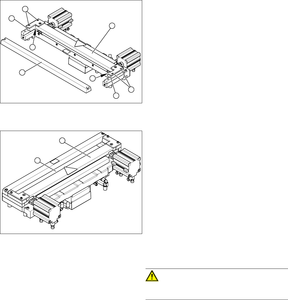
Final work
► Reinsert the tape deflector unit (3) and screw in the 4
hexagon socket-head screws (4) by hand.
► Push the spacers (with inserted shim) as far as pos-
sible in the direction of the moveable blade. The max-
imum permissible gap is 1.0 mm.
► In this position, tighten the 4 screws (4) on the tape
deflector holder crosswise (tightening torque).
► Remove the two shim rings.
► Insert the new stationary blade (5) in the correct po-
sition and screw tight.
1
2
4
1
5
4
3
2
► Use a feeler gauge to check the gap between the
tape deflector (1) and the moveable blade (2), along
the entire length and width of the blade.
⇨ The 0.05 mm feeler gauge should fit through the
gap.
⇨ The 0.25 mm feeler gauge should not fit through
the gap.
If the gap is not correct, check:
▪ Whether the wrong holding-down device has been in-
stalled (with function status < 03)
▪ The holding-down devices are those designed for
cutters with function status -04 (= with tape deflector)
▪ Whether the blades, tape deflector etc. were cleaned
before installation
If the gap is correct:
► Replace the protective sheet, deflector plate and cov-
er plate. Make sure that the edges are parallel.
CAUTION! Check how the cables are run!
Make sure that the cables and hoses are not pinched or
subjected to excess strain.
► Remove the clamps form the cutter/ remove the cut-
ter from the assembly plate.
► Fit the cutter.
1
2
Measuring Equipment and Tools
SIPLACE Axis Tester (SAT) [03002801-01]
Service Manual SIPLACE D1/D1i/D2/D2i 193
5
5 Measuring Equipment and Tools
Measuring Equipment and Tools
5.1
5.1 SIPLACE Axis Tester (SAT) [03002801-01]
SIPLACE Axis Tester (SAT) [03002801-01]
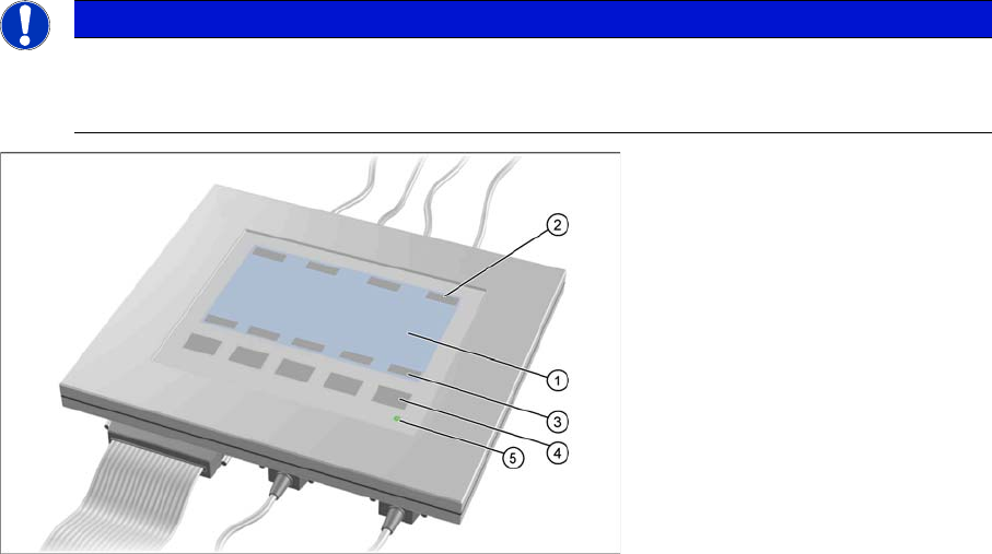
Axis tester - view from above
1. LCD display with 240 x 128 pixels, black-and-white display, with background illumination
The LCD display shows the menus and the recorded trigger, track and position signals. All relevant
parameters, such as
– Time basis,
– Time measurement values,
– Signal levels and
– Cursor positions with the corresponding time deviation values
are shown as alphanumerical data in the diagram of the measurement curves.
2. Dynamic function display of BNC socket arrangement on the LCD display
3. Dynamic function display of foil button arrangement on the LCD display
4. Five foil buttons for menu control
5. Green LED for displaying operation
NOTICE
A363, A364
The axis tester is designed for all machines with A363. This function is limited for machines
with A364.