00195376-05_SM_D1_D1i_D2_D2i_EN.pdf - 第203页
Settings 6.1.1 Checking the Firmware Function Electrical System Service Manual SIPLACE D1/D1i/D2/D2i 203 6 6 S e t t in g s Settings 6.1 6 . 1 E le c t r ic a l S y s t e m Electrical System 6.1.1 6 . 1 . 1 C h e c k in …
Measuring Equipment and Tools
Calibration Nozzle for TwinHead [03008862-xx] 5.1.1 Scope of Delivery
202 Service Manual SIPLACE D1/D1i/D2/D2i
Settings
6.1.1 Checking the Firmware Function Electrical System
Service Manual SIPLACE D1/D1i/D2/D2i 203
6
6 Settings
Settings
6.1
6.1 Electrical System
Electrical System
6.1.1
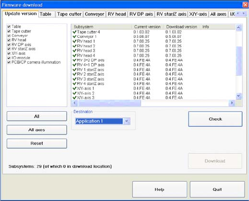
6.1.1 Checking the Firmware Function
Checking the Firmware Function
6.1.2
6.1.2 Firmware Download Note
Firmware Download Note
From the following station software versions, the firmware download can be performed to all CAN bus
nodes, via the standard SITEST interface.
▪ 505.04 SP2
▪ 603.01 SP1
▪ 604.01 SP1
6.2
6.2 Gantries
Gantries
6.2.1
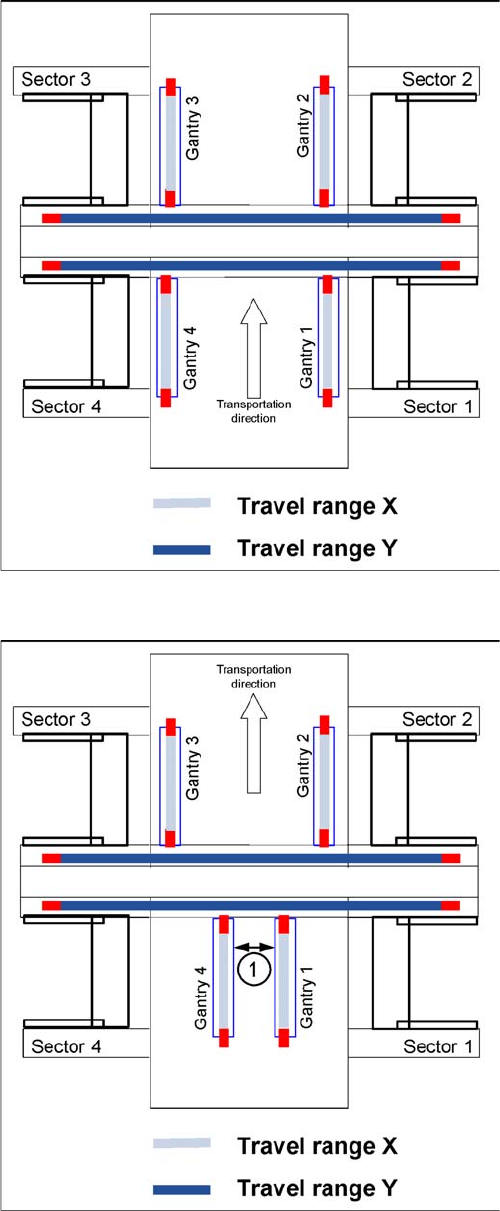
6.2.1 Travel Ranges and Speed Monitoring
Travel Ranges and Speed Monitoring
The travel range of the X and Y axes is determined automatically with the SITEST program.
This means that, during travel range calibration, the axis concerned moves as far as possible towards
the minimum or maximum position, until the set target value is no longer reached by the axis card. It is
then assumed that the hardware end stopper (bumper) has been reached. In a time window of approx.
10 ms, the greatest actual value achieved is taken to calculate the travel range.
To guarantee an appropriate safety distance before the hardware end stopper is touched, a certain dis-
tance is deducted from the set travel range. This enables the axis to brake in time, even when errors
occur.
► Select a Target (BIOS/application 1/application 2)
and click on the Check.
Settings
Gantries 6.2.1 Travel Ranges and Speed Monitoring
204 Service Manual SIPLACE D1/D1i/D2/D2i
Travel range for X and Y axes (D4 shown as example)
The end of the X-axis travel range is + or - 0.5 mm before
the bumper. This safety distance to the bumper is ade-
quate, if the X-axis moves into this area with excessive
speed.
The end of the Y-axis travel range is+ or - 1.5 mm before
the bumper. Monitoring of the Y-axis travel range in a
placement area is handled by software. There is a contin-
uous communication exchange between the two Y-axes
and their positions, via the SPI Bus.
Travel range for X and Y axes (D4 shown as example)
1. During travel range calibration, the X axis moves as
far as possible towards the minimum or maximum po-
sition, until it touches the bumper.
The travel ranges are calculated, taking into account
the relevant safety gap.
2. Gantry 1 moves just to the minimum position and
gantry 2 to the maximum position, for the Y-axis in the
placement area.
3. The minimum safety distance between the gantries,
during placement: minimum 4 mm.