00195376-05_SM_D1_D1i_D2_D2i_EN.pdf - 第206页
Settings Gantries 6.2.3 PCB Boards on the Gantry 206 Service Manual SIPLACE D1/D1i/D2/D2i 6.2.2.5 6 . 2 . 2 . 5 A n t ic r a s h F u n c t io n Anticrash Function 6.2.3 6 . 2 . 3 P C B B o a r d s o n t h e G a n t r y P…
Settings
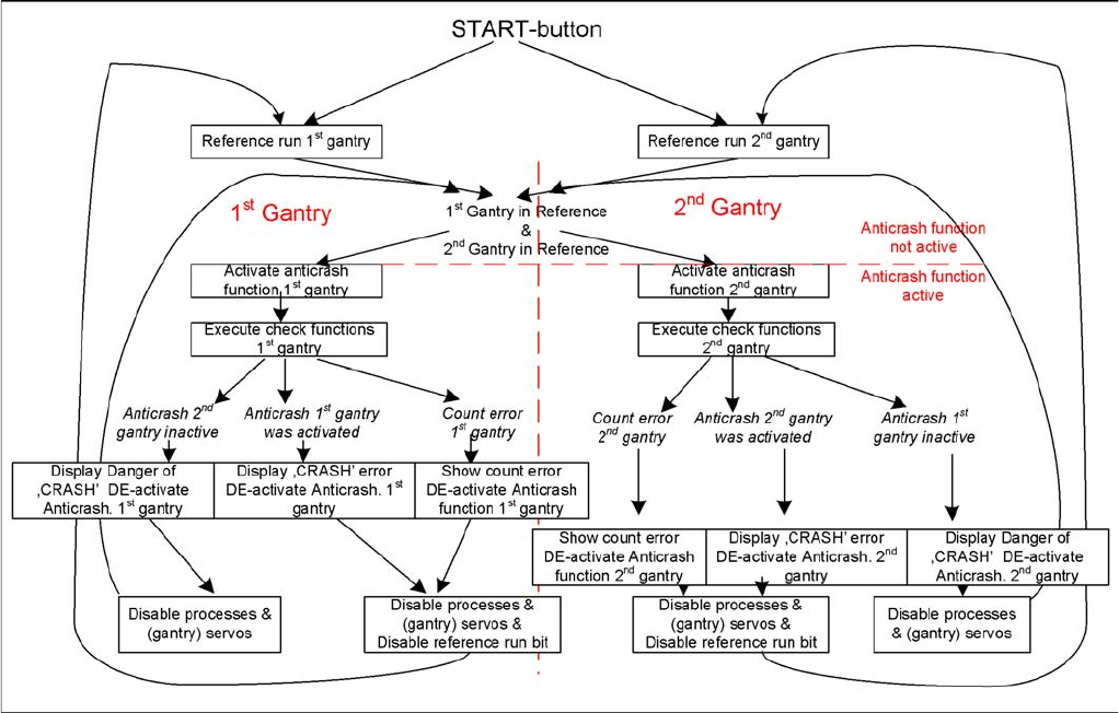
6.2.2 Anticrash Function for the A364 Axis Card Gantries
Service Manual SIPLACE D1/D1i/D2/D2i 205
6.2.2
6.2.2 Anticrash Function for the A364 Axis Card
Anticrash Function for the A364 Axis Card
6.2.2.1
6.2.2.1 Anticrash Function for the A364
Anticrash Function for the A364
▪ The anticrash function is no longer provided by the anticrash board but instead by the A364 software
(application 1). This means that the proximity switches used to monitor the travel range and the sen-
sor for monitoring the gantry spacing are no longer required.
▪ Tasks:
– Monitoring the X and Y axis travel ranges
Evaluation of the actual position of the respective axis in the direction of the bumper, based on
the speed.
– Monitoring the distance of both Y axes in a placement area
Evaluation of the actual position of the own gantry and the partner gantry at gantry crash moni-
toring.
– Count error monitoring of the gantry axis
Monitoring incoming count pulses (edge control) over time.
6.2.2.2
6.2.2.2 Anticrash Monitoring for the A364
Anticrash Monitoring for the A364
The anticrash function is activated after the X/Y axes have been referenced. When the gantry axes are
referenced for the first time, anticrash monitoring is not active, which does not matter, due to the low ref-
erence speed.
After this, the bit is set for the anticrash monitoring function and the actual position for the relevant part-
ner gantry is continuously communicated via the SPI Bus.
The following information is exchanged between the Y axes:
▪ Actual position and speed of the own gantry
▪ Status information (reference state, anticrash monitoring state ).
6.2.2.3
6.2.2.3 Error "Gantry Crash"
Error "Gantry Crash"
A “gantry crash” error is established by calculating the position difference and speed difference for both
axes. A gantry crash error is signaled via the axis card and the CAN Bus. The servo is released for both
axes and both need to be referenced again.
6.2.2.4
6.2.2.4 Count Error:
Count Error:
If the axis board detects a "fatal count error", the axis concerned will be released and the anticrash func-
tion disabled. The other axis is informed of this in the status information and will also disable the ant-
icrash function. The released axis now needs to be referenced again.
after which the anticrash function will be re-enabled for both axes.
Settings
Gantries 6.2.3 PCB Boards on the Gantry
206 Service Manual SIPLACE D1/D1i/D2/D2i
6.2.2.5
6.2.2.5 Anticrash Function
Anticrash Function
6.2.3
6.2.3 PCB Boards on the Gantry
PCB Boards on the Gantry
The boards on the gantry, as described below, are basically identical and do not depend on the head
configuration of D1, D2 and D4 machines. The CAN bus terminating resistor is fixed onto the gantry head
distributor.
Settings
6.2.3 PCB Boards on the Gantry Gantries
Service Manual SIPLACE D1/D1i/D2/D2i 207
6.2.3.1
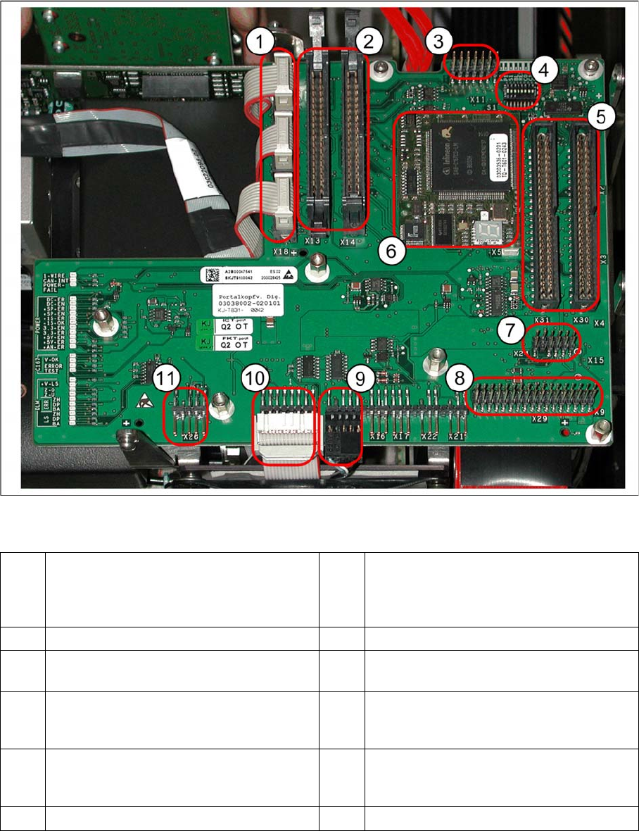
6.2.3.1 Gantry Head Distributor
Gantry Head Distributor
Legend
See also
6.2.3.1.1 DIP Switch on Gantry Head Distributor [ ➙ 208]
6.3.1.2.2 X24 on X-Axis Gantry Head Distributor [ ➙ 215]
1 X20 stepping motor - reject
X19 stepping motor (vacuum/air blast pick-
up
X18 stepping motor - swivel in
7 X24 Test connector for „digital track signals
for X-axis“
2 X13/X14 flat ribbon cable to C&P head 8 X29 connector for Vision board
3 X11 test connector for CAN Bus, SPI Bus,
RS232
9 X12 - DP station (motor, track signals)
4 8 fold DIP switch S1 (see "6.2.3.1.1 DIP
Switch on Gantry Head Distributor"
[ ➙ 208])
10 X10 - connector for vacuum board
5 X30/X31 flat ribbon cable for P&P head for
D1
(D4 not used)
11 X26 - component sensor option
6 TQM module (X5/X6 connector below)