00195376-05_SM_D1_D1i_D2_D2i_EN.pdf - 第208页
Settings Gantries 6.2.3 PCB Boards on the Gantry 208 Service Manual SIPLACE D1/D1i/D2/D2i DIP Switch on Gantry Head Distributor DIP switch DIP switch 3: ▪ ON : Test mode (without delay) ▪ OFF : Default state (with delay …
Settings
6.2.3 PCB Boards on the Gantry Gantries
Service Manual SIPLACE D1/D1i/D2/D2i 207
6.2.3.1
6.2.3.1 Gantry Head Distributor
Gantry Head Distributor
Legend
See also
6.2.3.1.1 DIP Switch on Gantry Head Distributor [ ➙ 208]
6.3.1.2.2 X24 on X-Axis Gantry Head Distributor [ ➙ 215]
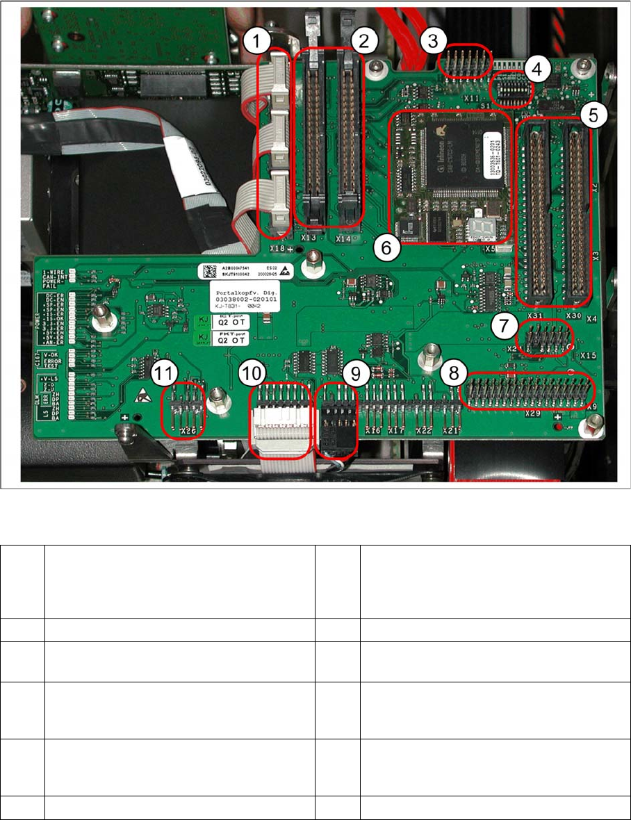
1 X20 stepping motor - reject
X19 stepping motor (vacuum/air blast pick-
up
X18 stepping motor - swivel in
7 X24 Test connector for „digital track signals
for X-axis“
2 X13/X14 flat ribbon cable to C&P head 8 X29 connector for Vision board
3 X11 test connector for CAN Bus, SPI Bus,
RS232
9 X12 - DP station (motor, track signals)
4 8 fold DIP switch S1 (see "6.2.3.1.1 DIP
Switch on Gantry Head Distributor"
[ ➙ 208])
10 X10 - connector for vacuum board
5 X30/X31 flat ribbon cable for P&P head for
D1
(D4 not used)
11 X26 - component sensor option
6 TQM module (X5/X6 connector below)
Settings
Gantries 6.2.3 PCB Boards on the Gantry
208 Service Manual SIPLACE D1/D1i/D2/D2i
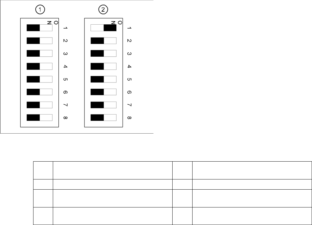
DIP Switch on Gantry Head Distributor
DIP switch
DIP switch 3:
▪ ON: Test mode (without delay)
▪ OFF: Default state (with delay of 3.6 ms+/- 300 us). Z-axis moves downwards, the top LB is released
and the LB down is enabled after a delay of 3.6 ms.
Legend
1. Gantry 1
2. Gantry 2 (for D2 only)
1 P0 – gantry ID0 address switch 1 --> gantry 5 Reset - CAN processor 16 Bit (TQM mod-
ule)
2 P1 – gantry ID1 address switch 2 --> gantry 6 C0 – no current function
3 S1 – switch for DLM head (delay switching
on LB down – Z-axis) (see below)
7 C1 – no current function
4 BL – enable boot loader for serial port 8 S2 – switch for DLM head (no current func-
tion)
Settings
6.2.3 PCB Boards on the Gantry Gantries
Service Manual SIPLACE D1/D1i/D2/D2i 209
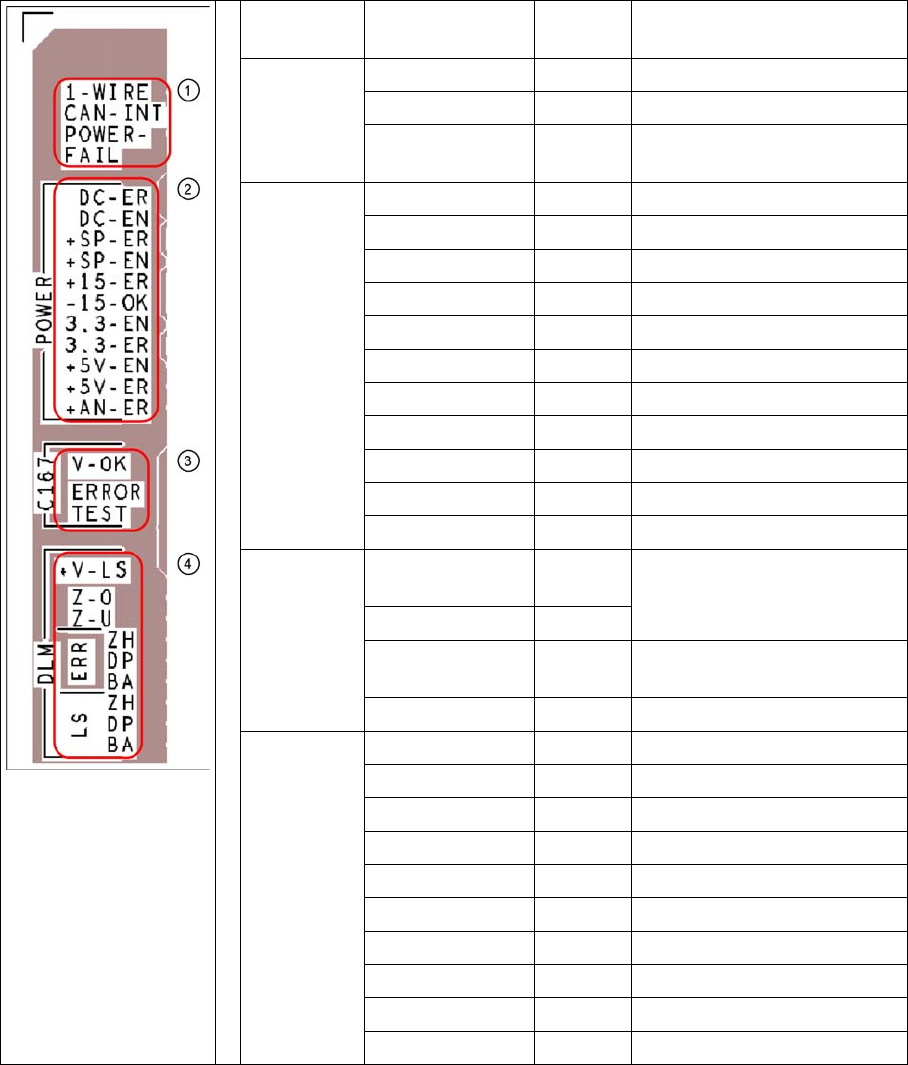
Description of LEDs on the Gantry Head Distributor
SM = stepping motor
Key PCB labeling LED sta-
tus
Description
1
CAN signal
1-WIRE Not in use
CAN-INT OFF not used
POWER-FAIL OFF Error +24 V power supply
(from the main machine)
2
Current sup-
ply
DC-ER OFF Error DC/DC converter
DC-EN ON Enable DC/DC converter
+SP-ER OFF Error +5V track encoder
+SP-EN ON Enable +5V track encoder
+15-ER OFF Error +15V
-15-OK ON -15V is OK
3.3-EN ON Enable +3.3V digital
3.3-ER OFF Error +3.3V digital
+5V-EN ON Enable +5 V digital
+5V-ER OFF Error +5V digital
+AN-ER OFF Error analog supply C167
3
Head
processor
V-OK ON
(green)
Internal voltage monitoring of
eSW
V-OK OFF
ERROR OFF
(red)
Error eSW
TEST Flashes Timer eSW in operation
4
LEDs
C&P head
functions
+V-LS ON OK + 15V light barrier
+V-LS OFF Error +15V light barrier
Z-O ON Z-axis is up
Z-U ON Z down has switched
ERR-ZH OFF Overload SM pickup
ERR-DP OFF Overload SM rotary axis
ERR-BA OFF Overload SM reject
LS-ZH ON Light barrier SM pickup
LS-DP ON Light barrier SM rotary axis
LS-BA ON Light barrier SM reject