00195376-05_SM_D1_D1i_D2_D2i_EN.pdf - 第212页
Settings Track Signals and Zero Pulse 6.3.1 Checking the Zero Pulse Signal 212 Service Manual SIPLACE D1/D1i/D2/D2i 6.3.1.1 6 . 3 . 1 . 1 M e a s u r in g t h e A n a lo g Z e r o P u ls e S ig n a l Measuring the Analog…

Settings
6.3.1 Checking the Zero Pulse Signal Track Signals and Zero Pulse
Service Manual SIPLACE D1/D1i/D2/D2i 211
6.2.3.4
6.2.3.4 Checking the DIP Switches
Checking the DIP Switches
DIP Switch on Vision Board
* Not all gantries may be available, depending on the machine type.
Mechanical Adjustment of the Incremental Encoder
The incremental encoders (read units) at the X and Y axes are mechanically set to a distance of 0.4 mm
+/- 0.1 mm and at the marked height to the incremental scale.
See also "4.2.8 Replacing the X-Axis Incremental Encoder (Read Head) [03047215S-xx]" [➙75] for the
diagram "casting marks on the incremental encoder".
6.3
6.3 Track Signals and Zero Pulse
Track Signals and Zero Pulse
6.3.1
6.3.1 Checking the Zero Pulse Signal
Checking the Zero Pulse Signal
The following description is only needed to check the electrical functions of the incremental encoder.
However, if the incremental encoder has been correctly fitted (mechanically), the unit should work with-
out errors.
S Setting for gantry* Comments
1 2 3 4
1 OFF OFF OFF OFF Boot mode - CAN processor 16
Bit via connector X11
2 OFF OFF OFF OFF Reset - CAN processor 16 Bit to
subboard
3OFF ON OFF ONP0 - Address switch 1 --> Gantry
4OFF OFF ON ONP1 - Gantry address switch 2
5 OFF OFF OFF OFF WPE - Write protect enable, cur-
rently OFF
6 OFF OFF OFF OFF CAN R - Switch terminator CAN
bus
7ONON ONONTest 1 - CAN 1 MBit/s --> ON
8ONON ONONTest 0 - CAN IDs --> ON
NOTICE
► To set this distance, use one or more small plastic disks with a total thickness of 0.4 mm.
► After setting the incremental scale, check the zero pulse and the track signals along the en-
tire travel range.
NOTICE
From 2007, machines will be equipped with a new incremental encoder (read head) (as in
SIPLACE D4). A larger measuring window allows you to compensate contaminants on the in-
cremental scale (up to approx. 3.5 mm).
Settings
Track Signals and Zero Pulse 6.3.1 Checking the Zero Pulse Signal
212 Service Manual SIPLACE D1/D1i/D2/D2i
6.3.1.1
6.3.1.1 Measuring the Analog Zero Pulse Signal
Measuring the Analog Zero Pulse Signal
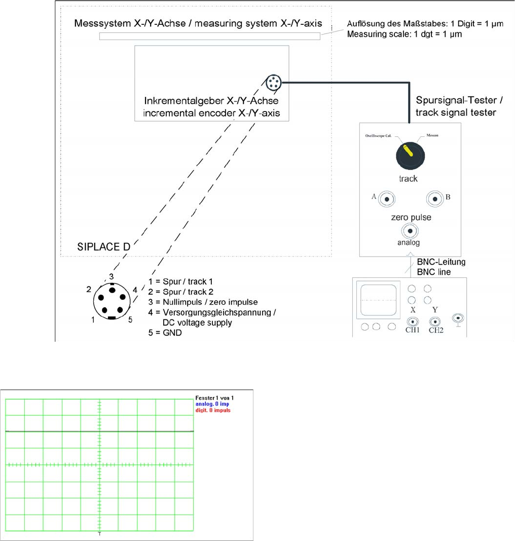
Measurement procedure for checking the analog zero pulse and the analog track signals
Measurement Procedure
Measuring the initial zero pulse position
► Oscilloscope settings:
CH1: Analog zero pulse
500 mV / 10 ms
CH2: Digital zero pulse
2 V / 10 ms
This should be triggered at CH1 with a trigger thresh-
old of approx. 2.5 V.
► Connect the measurement tester to the incremental
encoder.
► Main switch ON
► Connect the oscilloscope to the measurement tester.
► Set the measurement adapter to Calibrate oscillo-
scope and position the signal at the top, center of the
screen.
► Set the switch to "Measure".
► Manually move the gantry over the first zero pulse.
► The following picture should appear on the oscillo-
scope.
Settings
6.3.1 Checking the Zero Pulse Signal Track Signals and Zero Pulse
Service Manual SIPLACE D1/D1i/D2/D2i 213
6.3.1.2
6.3.1.2 Measuring the Digital Zero Pulse Signal
Measuring the Digital Zero Pulse Signal
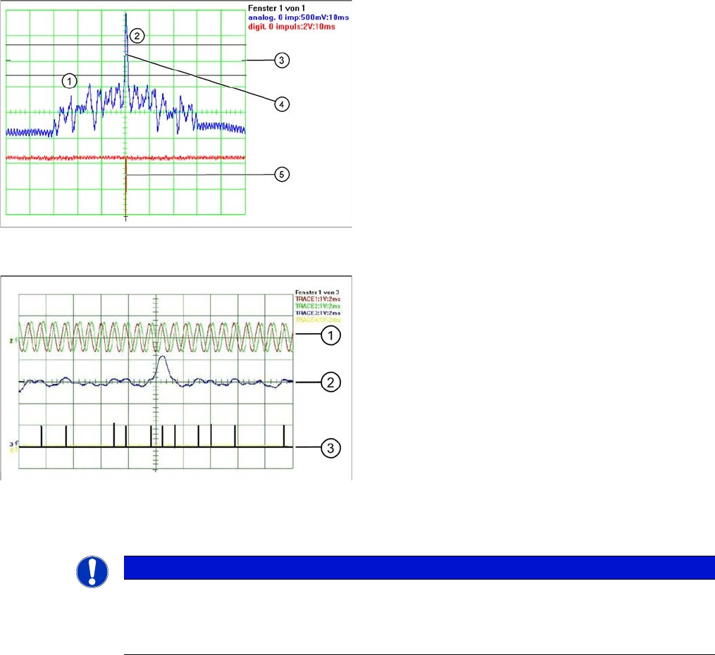
Correctly adjusted read unit
Legend
1. There should be no interference pulse in the toler-
ance space of - 0.3 V.
2. The analog zero pulse must exceed the tolerance
space by more then 0.3V.
3. Initial setting (calibrate oscilloscope)
4. Analog zero pulse
5. Digital zero pulse
The digital zero pulse is recorded by the axis test box,
which has been connected to the axis card of the respec-
tive axis. (See section.)
Incorrectly adjusted read unit or contaminated zero pulse
Legend
1. Analog track signal A and B
2. Analog zero pulse
3. Digital zero pulses
NOTICE
You can also use the BNC socket on the axis test box to check the zero pulse signal (inverted
display of zero pulse signal). The digital signals can be checked at connectors X11 and X24 of
the gantry distributor and gantry head distributor (for error monitoring purposes). (calculate ex-
tra time for Y axes, dismantling the covers).