00195376-05_SM_D1_D1i_D2_D2i_EN.pdf - 第221页
Settings 6.4.3 Checking the Y Axis Dynamics Axis Control Service Manual SIPLACE D1/D1i/D2/D2i 221 6.4.3 6 . 4 . 3 C h e c k in g t h e Y A x is D y n a m ic s Checking the Y Axis Dynamics 6.4.3.1 6 . 4 . 3 . 1 M e a s u …
Settings
Axis Control 6.4.2 Checking the X Axis Dynamics
220 Service Manual SIPLACE D1/D1i/D2/D2i
6.4.2.3
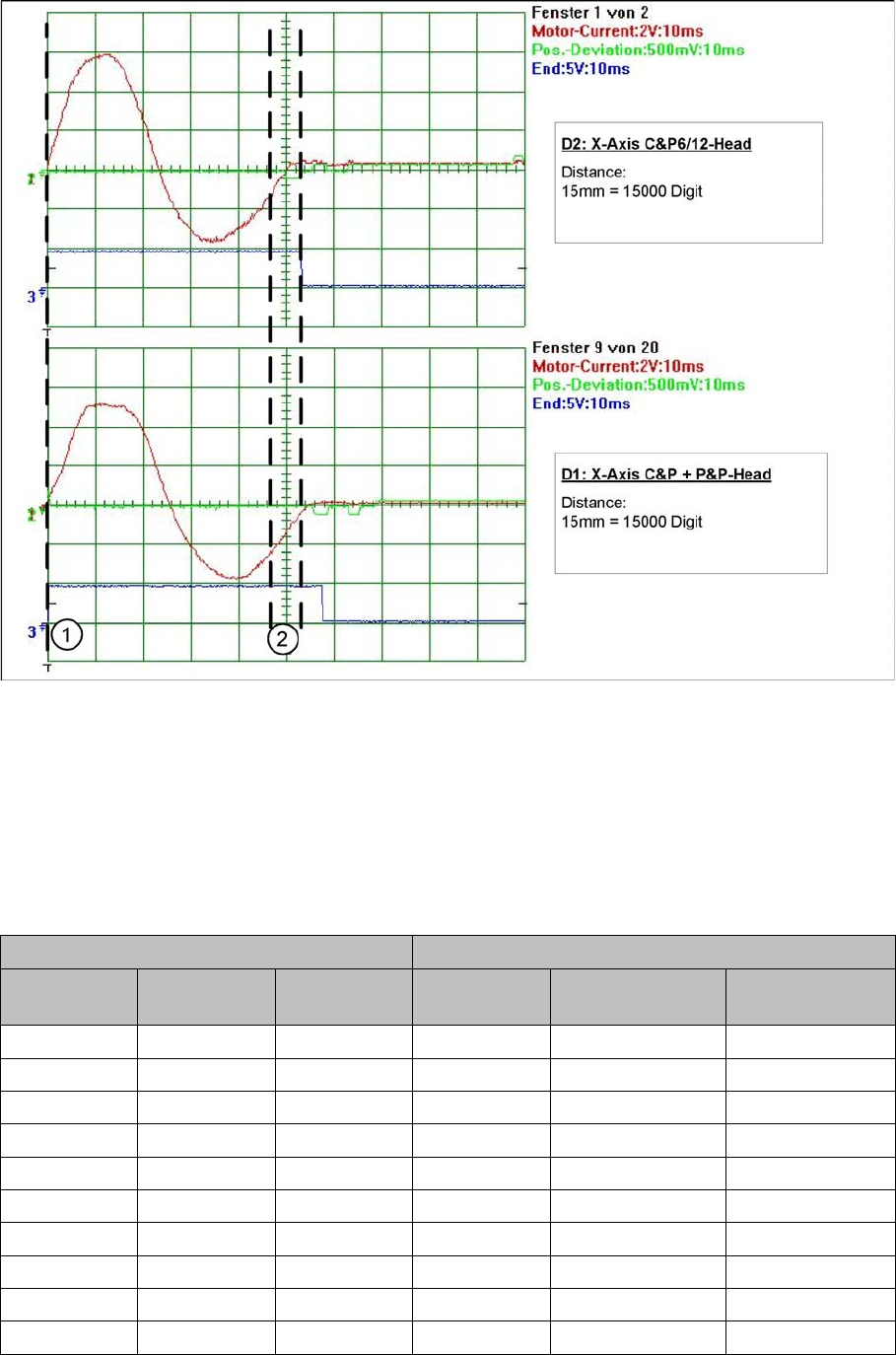
6.4.2.3 Comparison of X-Axis Travel Profile for C&P6/12 and P&P Heads
Comparison of X-Axis Travel Profile for C&P6/12 and P&P Heads
Signal path at 15000 digit travel range of X axis for different head configurations
Legend
1. Axis start
2. The end position signal is triggered at different times, depending on the axis records for both head
configurations.
6.4.2.4
6.4.2.4 X Axis Travel Time Table, According to Placement Heads
X Axis Travel Time Table, According to Placement Heads
Travel times for X gantry axis
D2 machine: C&P6 or C&P12 D1 machine: C&P6 or C&P12 + P&P
Distance / dig-
it
Target time /
ms
Tolerance /ms Distance / dig-
it
Target time / ms Tolerance /ms
500 33 +/-5 500 30 +/-5
1000 35 +/-5 1000 33 +/-5
2000 37 +/-5 2000 39 +/-5
5000 43 +/-5 5000 48 +/-5
15000 56 +/-5 15000 60 +/-5
20000 64 +/-10 20000 66 +/-10
50000 88 +/-10 50000 95 +/-10
100000 117 +/-10 100000 126 +/-10
200000 159 +/-15 200000 174 +/-15
300000 199 +/-15 300000 214 +/-15
Settings
6.4.3 Checking the Y Axis Dynamics Axis Control
Service Manual SIPLACE D1/D1i/D2/D2i 221
6.4.3
6.4.3 Checking the Y Axis Dynamics
Checking the Y Axis Dynamics
6.4.3.1
6.4.3.1 Measurement Setup
Measurement Setup
6.4.3.2
6.4.3.2 Y-axis Travel Profiles for C&P12 Head
Y-axis Travel Profiles for C&P12 Head
6.4.3.3
6.4.3.3 Y Axis Travel Time Table (D1/D2/D1i/D2i)
Y Axis Travel Time Table (D1/D2/D1i/D2i)
NOTICE
The measurement procedure follows the same preparations and procedures as for the X axis.
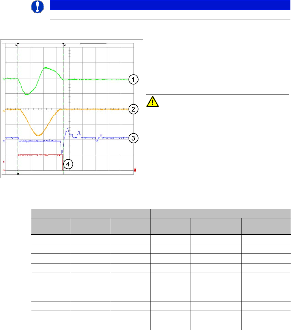
Example of y-axis signal path for 15000 digit path
Legend
1. Current signal
2. Speed – signal Vreg (Vnominal)
3. Deviation of position
4. End signal
Distance: 15mm = 15000 Digit
CAUTION! The permissible position deviation
for placement with a C&P12 head: 10 µm (digits)
D2/D2i: C&P6 or C&P12 D1/D1i: C&P6 or C&P12 and P&P
Distance / dig-
it
Target time /
ms
Tolerance /ms Distance / dig-
it
Target time / ms Tolerance /ms
500 45 +/-5 500 45 +/-5
1000 50 +/-5 1000 50 +/-5
2000 59 +/-5 2000 62 +/-5
5000 66 +/-5 5000 75 +/-5
15000 79 +/-10 15000 91 +/-10
20000 90 +/-10 20000 105 +/-10
50000 118 +/-10 50000 133 +/-10
100000 150 +/-10 100000 172 +/-10
200000 196 +/-15 200000 228 +/-15
600000 378 +/-15 600000 425 +/-15
Settings
Axis Control 6.4.4 Overview of Axis Control for Star, Z and DP Axis
222 Service Manual SIPLACE D1/D1i/D2/D2i
6.4.4
6.4.4 Overview of Axis Control for Star, Z and DP Axis
Overview of Axis Control for Star, Z and DP Axis
6.4.4.1
6.4.4.1 Positioning Time for C&P6 Head
Positioning Time for C&P6 Head
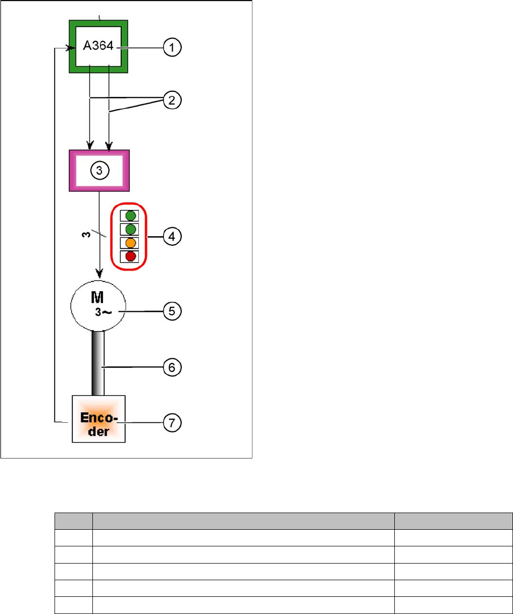
Star axis control system
The closed-loop control system for control of the head
axes consists of the following parts. The differences be-
tween the head axes will be explained later in this chap-
ter.
▪ Axis board A364
▪ Servo card
▪ Motor
▪ Measurement system (incremental scale and encod-
er (read unit)
Legend
1. Axis board A364
2. Control signals I target "W" and I target "U"
3. Servo amplifier
4. LEDs on servo amplifier:
5. 3 phase AC motor.
6. Between the motor and the incremental encoder
there is a fixed mechanical connection.
7. Incremental encoder: transmits the exact position of
the axis. The track signals are the only feedback sig-
nals for the axes.
The servo board controls the motor directly.
Axis Mode/range Positioning time
Star Axis continuous run / 1 star step 70 ms +/-3 ms
Z Absolute, free space / 685 digits 30 +/-3 ms
Z Light barrier, into calibration tool pocket / approx. 685 digits 30 +/-3 ms
DP 200 digits 38 ms +/-3 ms
DP 7200 digits 85 ms +/-3 ms