00195376-05_SM_D1_D1i_D2_D2i_EN.pdf - 第222页
Settings Axis Control 6.4.4 Overview of Axis Control for Star, Z and DP Axis 222 Service Manual SIPLACE D1/D1i/D2/D2i 6.4.4 6 . 4 . 4 O v e r v ie w o f A x is C o n t r o l f o r S t a r , Z a n d D P A x is Overview of…
Settings
6.4.3 Checking the Y Axis Dynamics Axis Control
Service Manual SIPLACE D1/D1i/D2/D2i 221
6.4.3
6.4.3 Checking the Y Axis Dynamics
Checking the Y Axis Dynamics
6.4.3.1
6.4.3.1 Measurement Setup
Measurement Setup
6.4.3.2
6.4.3.2 Y-axis Travel Profiles for C&P12 Head
Y-axis Travel Profiles for C&P12 Head
6.4.3.3
6.4.3.3 Y Axis Travel Time Table (D1/D2/D1i/D2i)
Y Axis Travel Time Table (D1/D2/D1i/D2i)
NOTICE
The measurement procedure follows the same preparations and procedures as for the X axis.
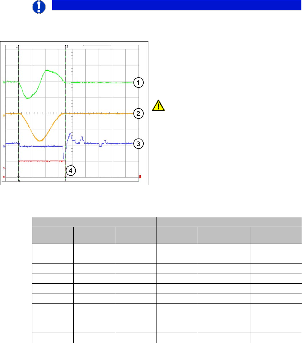
Example of y-axis signal path for 15000 digit path
Legend
1. Current signal
2. Speed – signal Vreg (Vnominal)
3. Deviation of position
4. End signal
Distance: 15mm = 15000 Digit
CAUTION! The permissible position deviation
for placement with a C&P12 head: 10 µm (digits)
D2/D2i: C&P6 or C&P12 D1/D1i: C&P6 or C&P12 and P&P
Distance / dig-
it
Target time /
ms
Tolerance /ms Distance / dig-
it
Target time / ms Tolerance /ms
500 45 +/-5 500 45 +/-5
1000 50 +/-5 1000 50 +/-5
2000 59 +/-5 2000 62 +/-5
5000 66 +/-5 5000 75 +/-5
15000 79 +/-10 15000 91 +/-10
20000 90 +/-10 20000 105 +/-10
50000 118 +/-10 50000 133 +/-10
100000 150 +/-10 100000 172 +/-10
200000 196 +/-15 200000 228 +/-15
600000 378 +/-15 600000 425 +/-15
Settings
Axis Control 6.4.4 Overview of Axis Control for Star, Z and DP Axis
222 Service Manual SIPLACE D1/D1i/D2/D2i
6.4.4
6.4.4 Overview of Axis Control for Star, Z and DP Axis
Overview of Axis Control for Star, Z and DP Axis
6.4.4.1
6.4.4.1 Positioning Time for C&P6 Head
Positioning Time for C&P6 Head
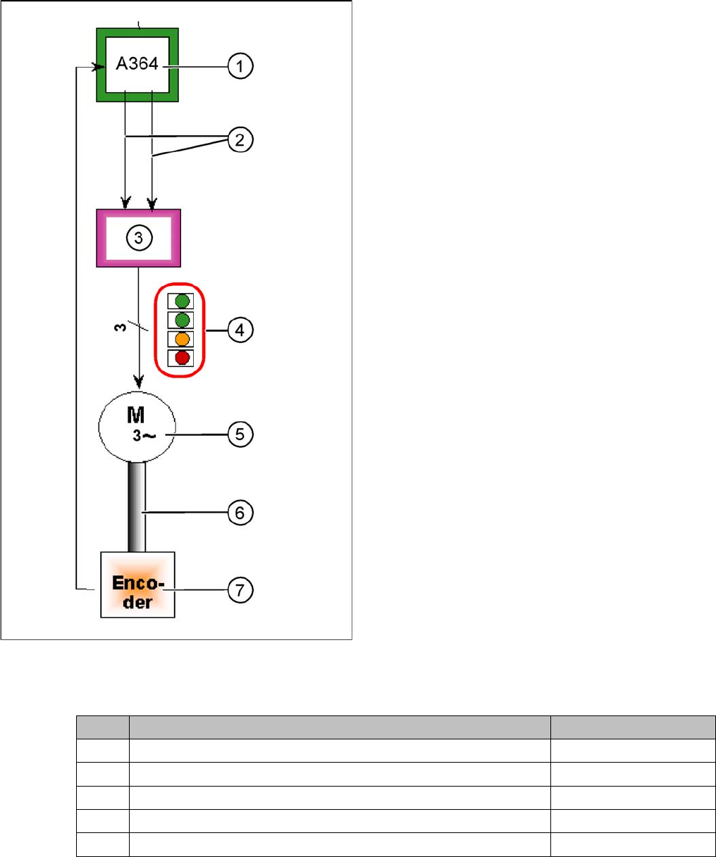
Star axis control system
The closed-loop control system for control of the head
axes consists of the following parts. The differences be-
tween the head axes will be explained later in this chap-
ter.
▪ Axis board A364
▪ Servo card
▪ Motor
▪ Measurement system (incremental scale and encod-
er (read unit)
Legend
1. Axis board A364
2. Control signals I target "W" and I target "U"
3. Servo amplifier
4. LEDs on servo amplifier:
5. 3 phase AC motor.
6. Between the motor and the incremental encoder
there is a fixed mechanical connection.
7. Incremental encoder: transmits the exact position of
the axis. The track signals are the only feedback sig-
nals for the axes.
The servo board controls the motor directly.
Axis Mode/range Positioning time
Star Axis continuous run / 1 star step 70 ms +/-3 ms
Z Absolute, free space / 685 digits 30 +/-3 ms
Z Light barrier, into calibration tool pocket / approx. 685 digits 30 +/-3 ms
DP 200 digits 38 ms +/-3 ms
DP 7200 digits 85 ms +/-3 ms
Settings
6.4.5 Track Signals for Head Axes Axis Control
Service Manual SIPLACE D1/D1i/D2/D2i 223
6.4.4.2
6.4.4.2 Positioning Time for C&P12 Head
Positioning Time for C&P12 Head
6.4.5
6.4.5 Track Signals for Head Axes
Track Signals for Head Axes
The track signals play a greater role with the new drive concept for SIPLACE machines. They are re-
sponsible for the exactly and precise positioning of the axes and are used as the only feedback signal
in the closed-loop control system, meaning that they have an important influence on the axis dynamics.
6.4.5.1
6.4.5.1 Overview
Overview
Oscilloscope settings
6.4.5.2
6.4.5.2 Measurement Setup
Measurement Setup
The head axis track signals can only be measured as digital signals i.e. the analog signals are converted
into digital signals in the read unit.
Axis Mode/path Positioning time
Star Axis continuous run / 1 Star step 43ms +/-3ms
Z Absolute, free space / 685 digits 21ms, -1ms
Z Light barrier, into calibration tool pocket / approx. 685 digits 21 +/-3ms
DP 100 digits 13ms +/-3ms
DP 3600 digits 39ms +/-3ms
Axes Mechanical settings Oscilloscope diagram
Star 25x: resolution 1/1000° Digital track signal amplitude 3.6Vpp
Z nothing Digital track signal amplitude 3.6Vpp
DP Incremental encoder set to 1.5 mm, paral-
lel to the glass
Digital track signal amplitude 3.6Vpp
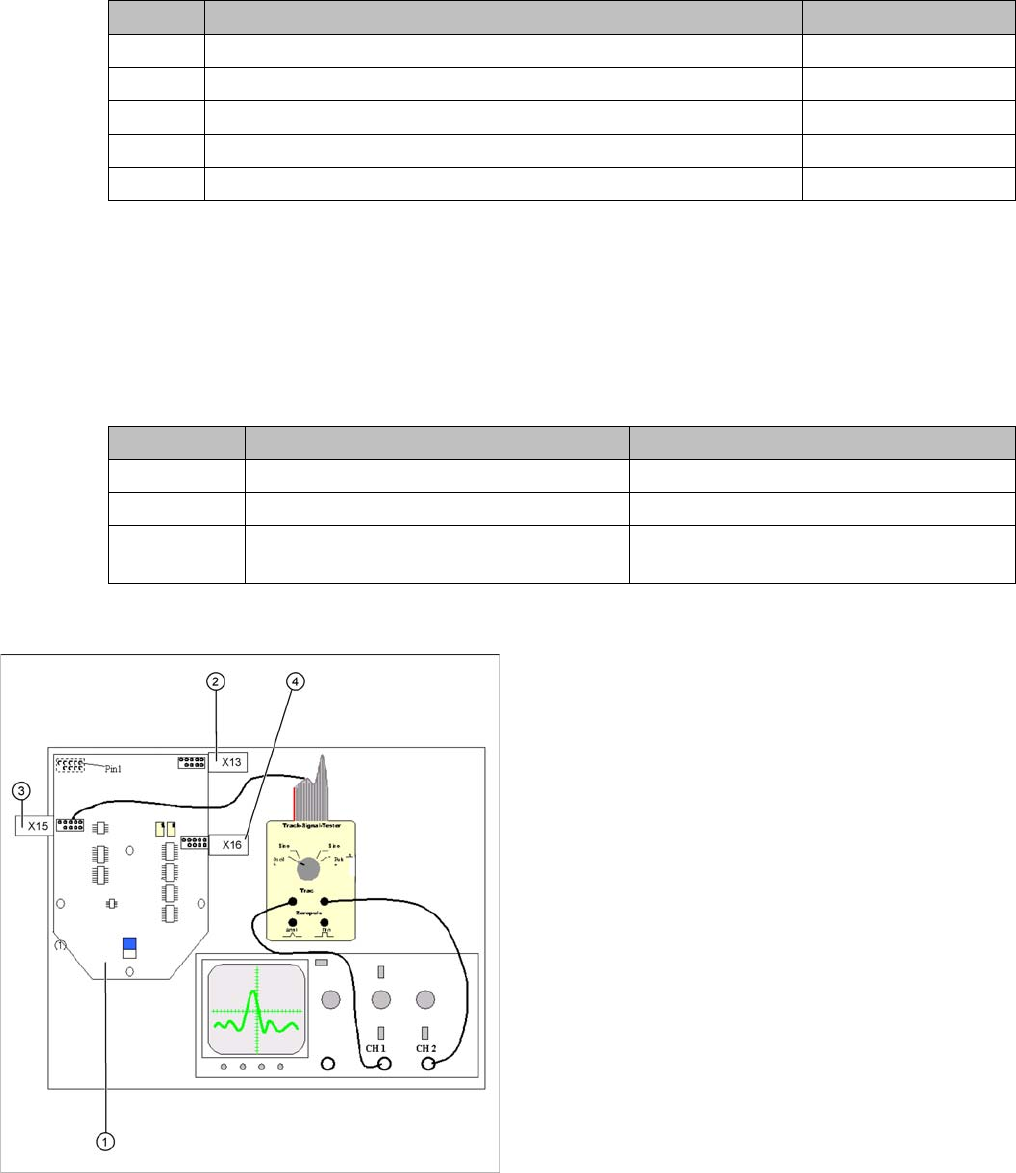
General measurement structure for checking track sig
-
nals
Legend
1. Intermediate distributor SP 6-12, digital
2. X13: track signal Z axis
3. X15: track signal star axis
4. X16: track signals DP axis
Use the track signal tester [00322510-xx] to test the head
axis track signals.
Assignment of connectors X13, X15, X16:
1. Ground
2. Track A
3. Track A
4. Ground
5. Track B
6. Track B
7. +5 V
8. Track N
9. Track N
10. Pin removed