00195376-05_SM_D1_D1i_D2_D2i_EN.pdf - 第228页
Settings Axis Control 6.4.7 Axis Control of Z Axis 228 Service Manual SIPLACE D1/D1i/D2/D2i Signal Example with the Vnom. Output C&P12 – Z axis in free space Dynamic signals for Z-axis in example of C&P6 head Leg…
Settings
6.4.7 Axis Control of Z Axis Axis Control
Service Manual SIPLACE D1/D1i/D2/D2i 227
6.4.7
6.4.7 Axis Control of Z Axis
Axis Control of Z Axis
6.4.7.1
6.4.7.1 Checking the Z Axis Dynamics
Checking the Z Axis Dynamics
Measurement Setup
The positioning time for the Z-axis is 21 +/-1 ms for the C&P12 head.
► Position the gantries so that the Z axis moves in a free space.
SITEST
► Select C&P heads ==> Select head ==> Axis functions
==> Select the Z axis ==> Select the permanent axis run, edit the values in digits and accept. Target
position = 685 digits and Position mode = absolute.
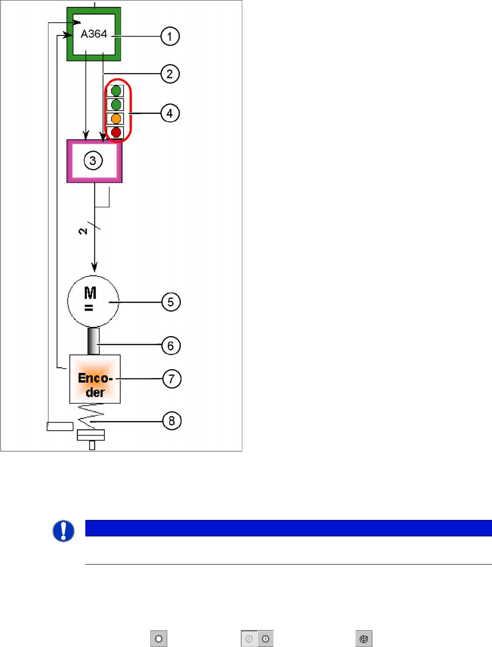
Axis control of Z axis
The Z axis is driven via a DC servo motor. Activation is
via a control signal (second control signal = 0) from the
processor of the A364 I
target "W"
and I
target "U"
= 0. The
intermediate circuit voltage is approx. 60V.
Legend
1. Axis board A364
2. Control signal I nom "W"
3. Servo amplifier
4. LEDs on servo amplifier:
5. DC motor.
6. Between the motor and the incremental encoder
there is a fixed mechanical connection.
7. Incremental encoder: transmits the exact position of
the axis (track signals).
8. Elastic mech. connection (belt) and light barrier
down, for fast recognition of the lower position.
The servo board controls the DC motor directly.
NOTICE
The measurement procedure follows the same preparations and procedures as for the star ax-
is.
Settings
Axis Control 6.4.7 Axis Control of Z Axis
228 Service Manual SIPLACE D1/D1i/D2/D2i
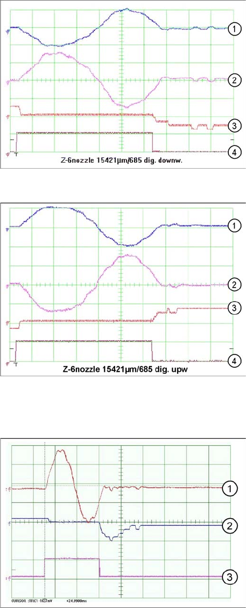
Signal Example with the Vnom. Output
C&P12 – Z axis in free space
Dynamic signals for Z-axis in example of C&P6 head
Legend
1. Control signal (at V nom. axis test box)
2. Uncommutated current signal at axis adapter
3. Deviation of position
4. End signal
Dynamic signals for Z-axis in example of C&P6 head
Legend
1. Control signal (at V nom. axis test box)
2. Uncommutated current signal at axis adapter
3. Deviation of position
4. End signal
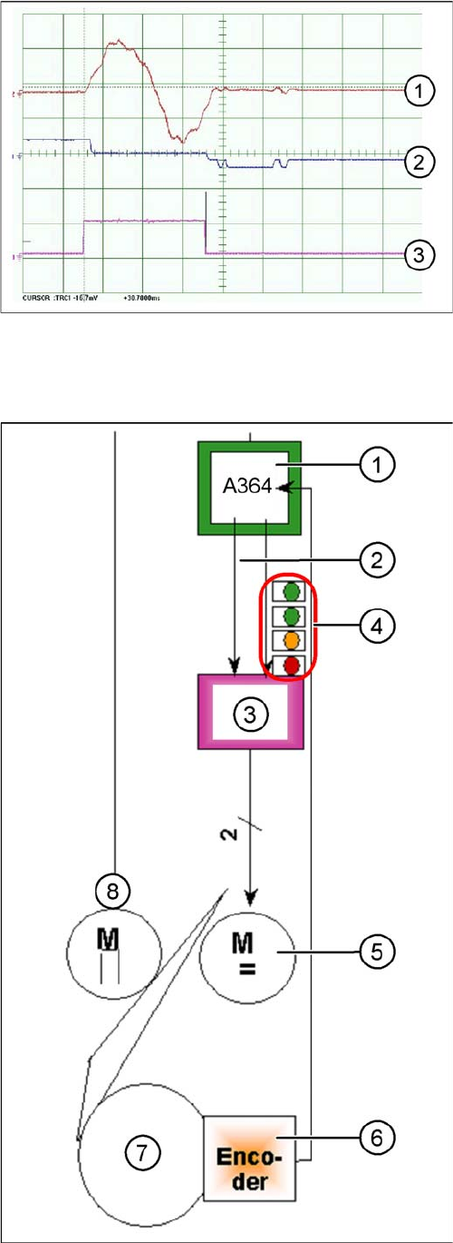
Travel curves for Z-axis of C&P12 head, in free space
Legend
1. Current target value: 2V/Div
2. Deviation of position 500mV/Div
3. End signal
Time basis: 10ms/Div
Target positioning time: 24 ms -1 ms
Range: 685 digits
Settings
6.4.8 Axis Control of DP Axis Axis Control
Service Manual SIPLACE D1/D1i/D2/D2i 229
C&P6 – Z axis
6.4.8
6.4.8 Axis Control of DP Axis
Axis Control of DP Axis
Travel curves for Z-axis of C&P6 head, in free space
Legend
1. Current target value: 2V/Div
2. Deviation of position 500mV/Div
3. End signal
Time basis: 10ms/Div
Target positioning time: 30 ms +/- 3 ms
Range: 685 digits
Axis control of DP axis
The DP axis is driven via a DC servo motor. Activation is
via a control signal (second control signal = 0) from the
processor of the A364 I
target "W"
and I
target "U"
= 0. The
intermediate circuit voltage is approx. 60V. Via a stepping
motor, the DP axis is coupled to the glass of the segment.
The DP axis positions the segment and is then decoupled
via the stepping motor.
Legend
1. Axis board A364
2. Control signal I nom "W"
3. Servo amplifier
4. LEDs on servo amplifier:
5. DC motor.
6. Incremental encoder: transmits the exact position of
the axis (track signals).
7. Segment glass
8. Swivel in
The servo board controls the DC motor directly.