00195376-05_SM_D1_D1i_D2_D2i_EN.pdf - 第232页
Settings Collect&Place Head 6.5.1 Calibrating the C&P Head and Cameras 232 Service Manual SIPLACE D1/D1i/D2/D2i C&P6 - for DP axis, 7200 digits 6.5 6 . 5 C o lle c t & P la c e H e a d Collect&Place H…
Settings
6.4.8 Axis Control of DP Axis Axis Control
Service Manual SIPLACE D1/D1i/D2/D2i 231
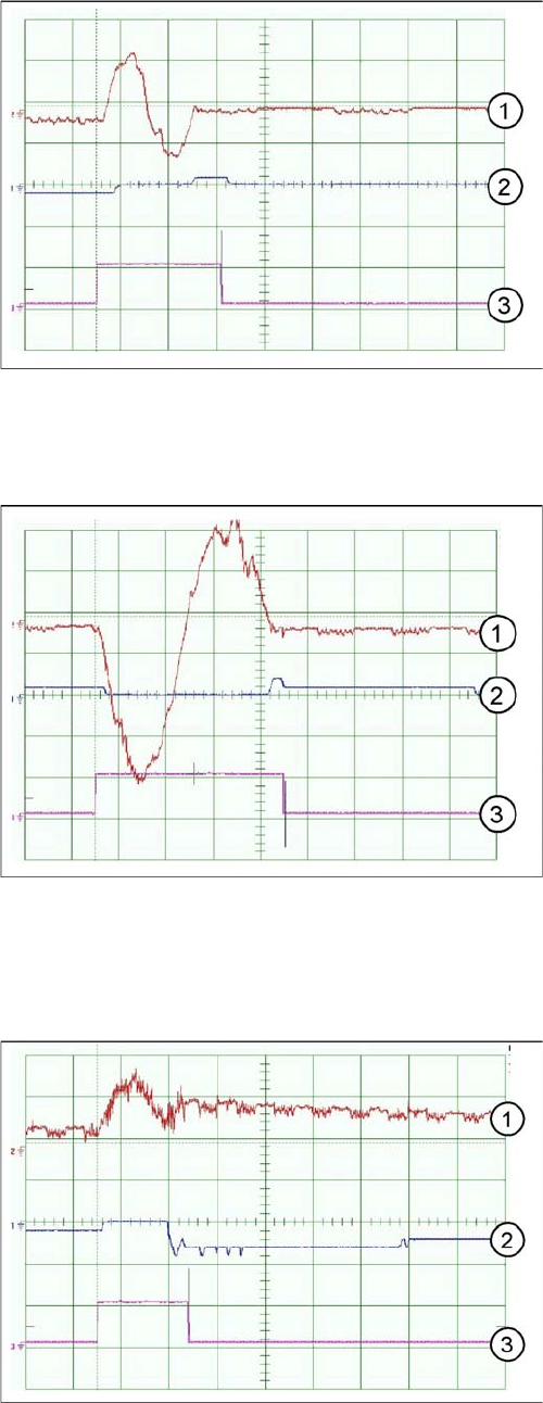
12er C&P head DLM2 - signal for DP axis, 100 digits
12er C&P head DLM2 - signal for DP axis, 3600 digits
C&P6 - for DP axis, 200 digits
Travel curves for DP axis, 100 digits for C&P12 head
Legend
1. Current target value: 200mV/Div
2. Deviation of position 500mV/Div
3. End signal
Time basis: 5ms/Div
Target positioning time: 13ms +/-3ms
Range: 100 digits
Travel curves for DP axis, 90 degrees rotation, C&P12
head
Legend
1. Current target value: 200mV/Div
2. Deviation of position 500mV/Div
3. End signal
Time basis: 10ms/Div
Target positioning time: approx. 46 ms +/-3 ms
Range: 3600 digits
Travel curves for DP axis, 200 digits for C&P6 head
Legend
1. Current target value: 100mV/Div
2. Deviation of position 500mV/Div
3. End signal
Time basis: 20 ms/Div
Target positioning time: 38 ms +/-3 ms
Range: 200 digits
Settings
Collect&Place Head 6.5.1 Calibrating the C&P Head and Cameras
232 Service Manual SIPLACE D1/D1i/D2/D2i
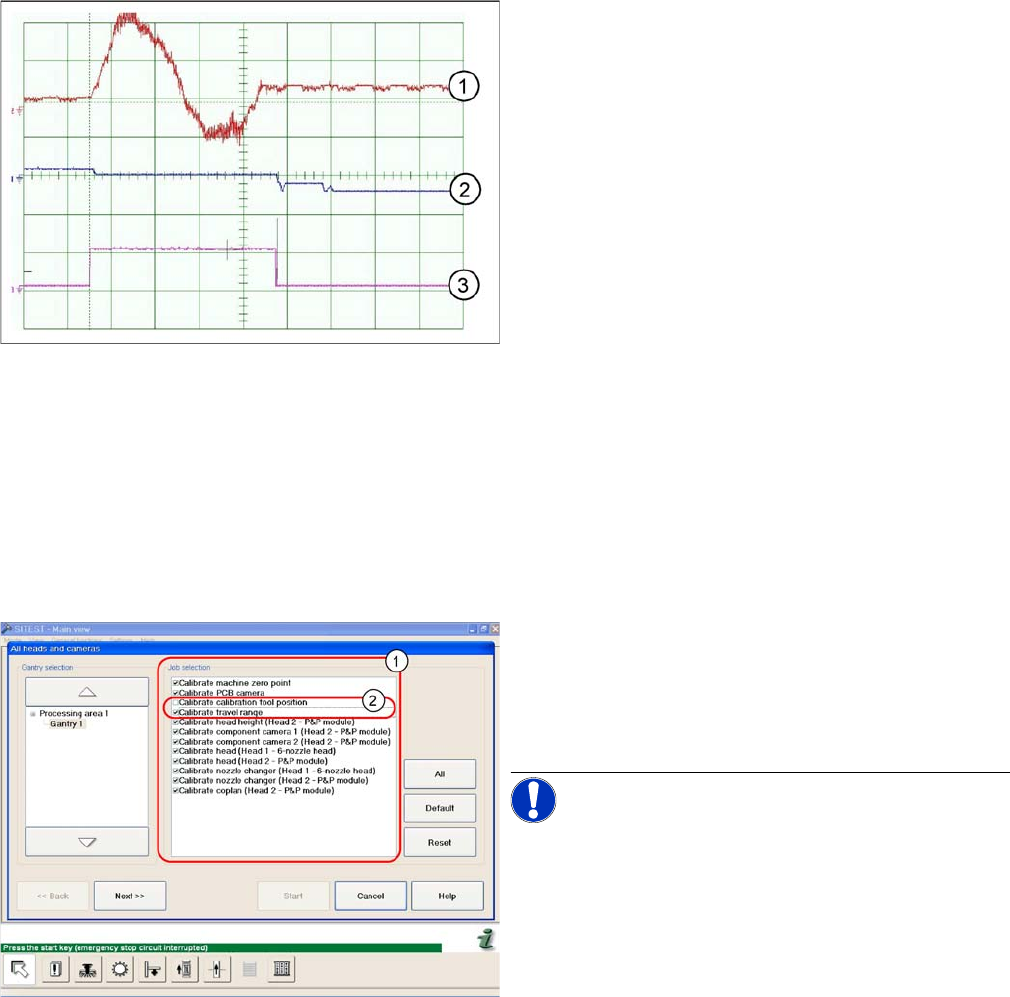
C&P6 - for DP axis, 7200 digits
6.5
6.5 Collect&Place Head
Collect&Place Head
6.5.1
6.5.1 Calibrating the C&P Head and Cameras
Calibrating the C&P Head and Cameras
Automatic calibration of all heads and cameras
Travel curves for DP axis, 90 degrees rotation, C&P6
head
Legend
1. Current target value: 200mV/Div
2. Deviation of position 500mV/Div
3. End signal
Time basis: 20 ms/Div
Target positioning time: 85 ms +/-3 ms
Range: 7200 digits
The menu may vary, according to the machine type and
configuration.
► In the SITEST menu, select Calibrate Entire Machine
--> All Heads and Cameras to open the adjacent
menu.
► In Job Selection (1) , select the components to be cal-
ibrated.
NOTICE! These two entries (2) are optional.

Settings
6.5.2 PCB Boards on the 6/12 C&P Head Collect&Place Head
Service Manual SIPLACE D1/D1i/D2/D2i 233
6.5.2
6.5.2 PCB Boards on the 6/12 C&P Head
PCB Boards on the 6/12 C&P Head
See also
4.4.4 Replacing the Intermediate Distributor [ ➙ 119]
6.2.3.1 Gantry Head Distributor [ ➙ 207]
6.5.3
6.5.3 Overview of Settings on the C&P6/12
Overview of Settings on the C&P6/12
► To continue calibration with manual handling, select
the four consecutive menus in Section Positions (1)
and the two menu items in the Section Mapping (2).
Description Tools and equipment Values
Mount the star onto the motor
shaft of the star motor
Adjust with the power pack and
star zero point gauge
Check the magnetic neutral posi-
tion in SITEST
(max. deviation 95 digits)
Determine zero point correction
for the star.
Gauge for zero point correction /
SITEST
Enter result of zero point correc-
tion with SITEST
--> enter positions.
Switch position on star motor
(resolution of track signals 10 -
25)
none HF/X/D machines at"6.5.4 Set-
ting the Resolution on the Star
Axis" [ ➙ 234]25
DP axis incremental encoder ad-
justment to the glass scale (seg-
ment)
Test probe 1.4 - 1.6 mm Distance 1.5 mm.
Adjustment mechanical position
of valve positioning drives
Distance gauge 0.2 mm or ad-
justment plunger
0.2 mm distance plunger to the
valve frame
Light barrier Z axis down Test probe 1.0 mm Distance 1.0 mm.
Clamping device on Z belt --- Tension jack must lie on the belt
teeth at the top and bottom.
Belt tension of the Z axis Belt tension measurement de-
vice
Belt tension 280 +/- 5 Hz
Z axis top stop Gauge for Z axis end stopper -
star gauge [03019865-xx]
Correct position is necessary to
determine the zero point correc-
tion.
Air blast tubes on the star Check with your eyes Check the distance between in-
cremental encoder and air blast
tubes.
Adjustment of air blast supply Feeler gauge Air blast tubes should be approx.
0.7 mm over the frame of the cir-
cular arc guide