00195376-05_SM_D1_D1i_D2_D2i_EN.pdf - 第24页
Overview Electrical System 3.2.3 Power Supply Unit 24 Service Manual SIPLACE D1/D1i/D2/D2i 3.2.3 3 . 2 . 3 P o w e r S u p p ly U n it Power Supply Unit 3.2.3.1 3 . 2 . 3 . 1 S u p p ly V o lt a g e s Supply Voltages The…
Overview
3.2.2 Computer Unit Electrical System
Service Manual SIPLACE D1/D1i/D2/D2i 23
3.2.2
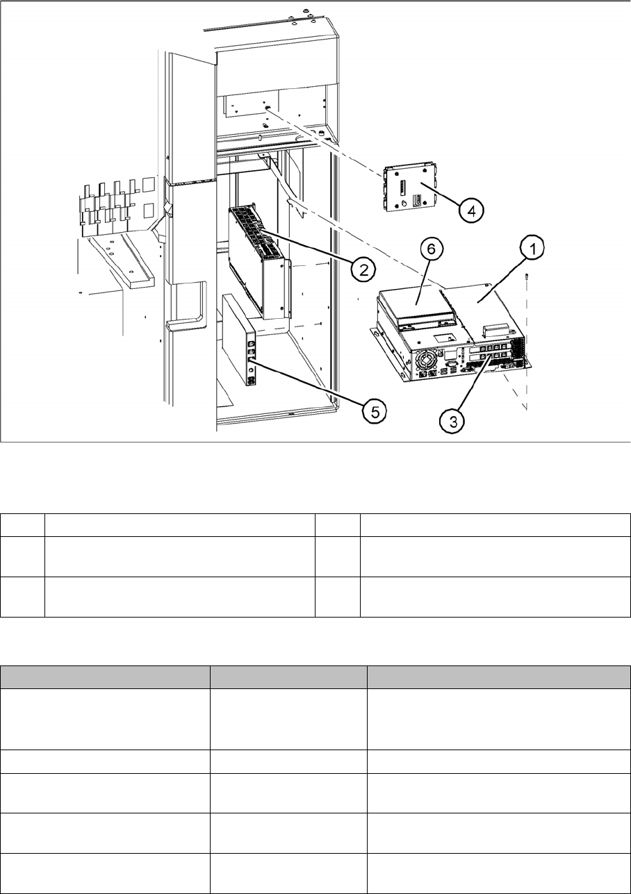
3.2.2 Computer Unit
Computer Unit
Computer unit
Legend
Overview of Settings
1 Station computer [03032341-xx] (Box PC) 4 Video multicoupler [03040316-xx]
2 Machine controller [03047697-xx]
(Micro Box PC)
5 USB hub 2.0 [03032344-xx]
3 Hotlink interface [03032343-xx] 6 Portables USB/DVD/CD drive
[03051205-xx]
Description Setting Comments
Station computer replaced No settings required Backup of machine data
Install software according to respective in-
stallation guide.
Video multiplexer replaced No settings required
Hotlink interface replaced No settings required Make sure that card engages correctly in
the slot.
USB hub 2.0 replaced No settings required Make sure that the USB hub is connected
to the bottom left USB port.
Machine controller replaced No settings required Software installation for machine control-
ler
Overview
Electrical System 3.2.3 Power Supply Unit
24 Service Manual SIPLACE D1/D1i/D2/D2i
3.2.3
3.2.3 Power Supply Unit
Power Supply Unit
3.2.3.1
3.2.3.1 Supply Voltages
Supply Voltages
The power supply unit provides the following supply voltages:
▪ 200 V for the servo amplifier of the X and Y axes in the axis unit
▪ 150 V / 4 V- for the servo amplifier of the star in the axis unit
▪ 40 V for the servo amplifier of the Z and DP axes in the axis unit
▪ 52 V for the DC/DC converter in the subdistributor
▪ 40 V for the changeover tables and the PCB handling system
▪ 8 V for the changeover tables
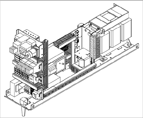
Power supply unit
The power supply unit is located in the left of the central
machine section. A lockable door prevents unauthorized
access to the unit.
Overview
3.2.3 Power Supply Unit Electrical System
Service Manual SIPLACE D1/D1i/D2/D2i 25
3.2.3.2
3.2.3.2 Position of Protective Contactor Combination and Service Socket
Position of Protective Contactor Combination and Service Socket
Service socket
The service socket is located in the power supply unit and is protected by the cover. It can only be used
if the placement system is connected to the main power supply via a 5-wire connection (L1, L2, L3, N,
and PE). If a 4-wire connection is used - without N - the socket can not be used.
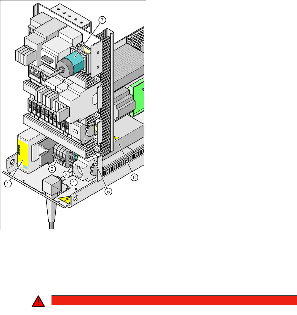
Position of protective contactor combination and service
socket
Legend
1. Protective contactor combination K1
2. Fuses FU, FV, FW, FBU
3. Infeed terminal X1
4. BU1 service socket
5. Z2 reactor
6. Main power filter Z1
7. S1 main power switch
Protective contactor combination 3TK2825
The protective contactor combination is located in the
power supply unit. It is used to monitor the EMERGENCY
STOP circuits and safety equipment.
There are three conditions that must be fulfilled in order
to activate the protective contactor combination:
▪ The "software enable" signal must have been sent.
▪ The EMERGENCY STOP loop must be closed.
▪ The start button must have been pressed.
The front side of the protective contactor combination has
three green LEDs for displaying the operational mode:
▪ The "Power" LED indicates that voltage is present.
▪ The "Channel 1" and "Channel 2" LEDs light up if the
start button has been pressed, the EMERGENCY
STOP loop is closed and the signaling circuit is not
signaling a fault status.
DANGER
Observe the safety instructions for lethal voltages, even when the machine is switched off.