00195376-05_SM_D1_D1i_D2_D2i_EN.pdf - 第247页
Settings 6.6.3 Parameter and Calibrations Pick&Place Head Service Manual SIPLACE D1/D1i/D2/D2i 247 6.6.3 6 . 6 . 3 P a r a m e t e r a n d C a lib r a t io n s Parameter and Calibrations 6.6.3.1 6 . 6 . 3 . 1 O v e r…

Settings
Pick&Place Head 6.6.2 DIP Switch for Camera Types 25, 33 and 36
246 Service Manual SIPLACE D1/D1i/D2/D2i
* Not all gantries may be available, depending on the machine type.
S Setting for gantry* Comments
1 2 3 4
1OF
F
OFF OF
F
OFF Bootstrap
2OF
F
OFF OF
F
OFF Reset
3OF
F
ON OF
F
ON Gantry ID 0
4OF
F
OFF ON ON Gantry ID 1
5OF
F
OFF OF
F
OFF Code 1
6OF
F
OFF OF
F
OFF CAN terminator
7ON ON ON ON CAN speed:ON:1 Mbit/s, OFF: 500 KB/s
8 xx xx xx xx x = OFF: FC camera (Type 25),
x = ON: IC camera (type 33, 36)
Settings
6.6.3 Parameter and Calibrations Pick&Place Head
Service Manual SIPLACE D1/D1i/D2/D2i 247
6.6.3
6.6.3 Parameter and Calibrations
Parameter and Calibrations
6.6.3.1
6.6.3.1 Overview of Calibration Steps and Parameters in SITEST
Overview of Calibration Steps and Parameters in SITEST
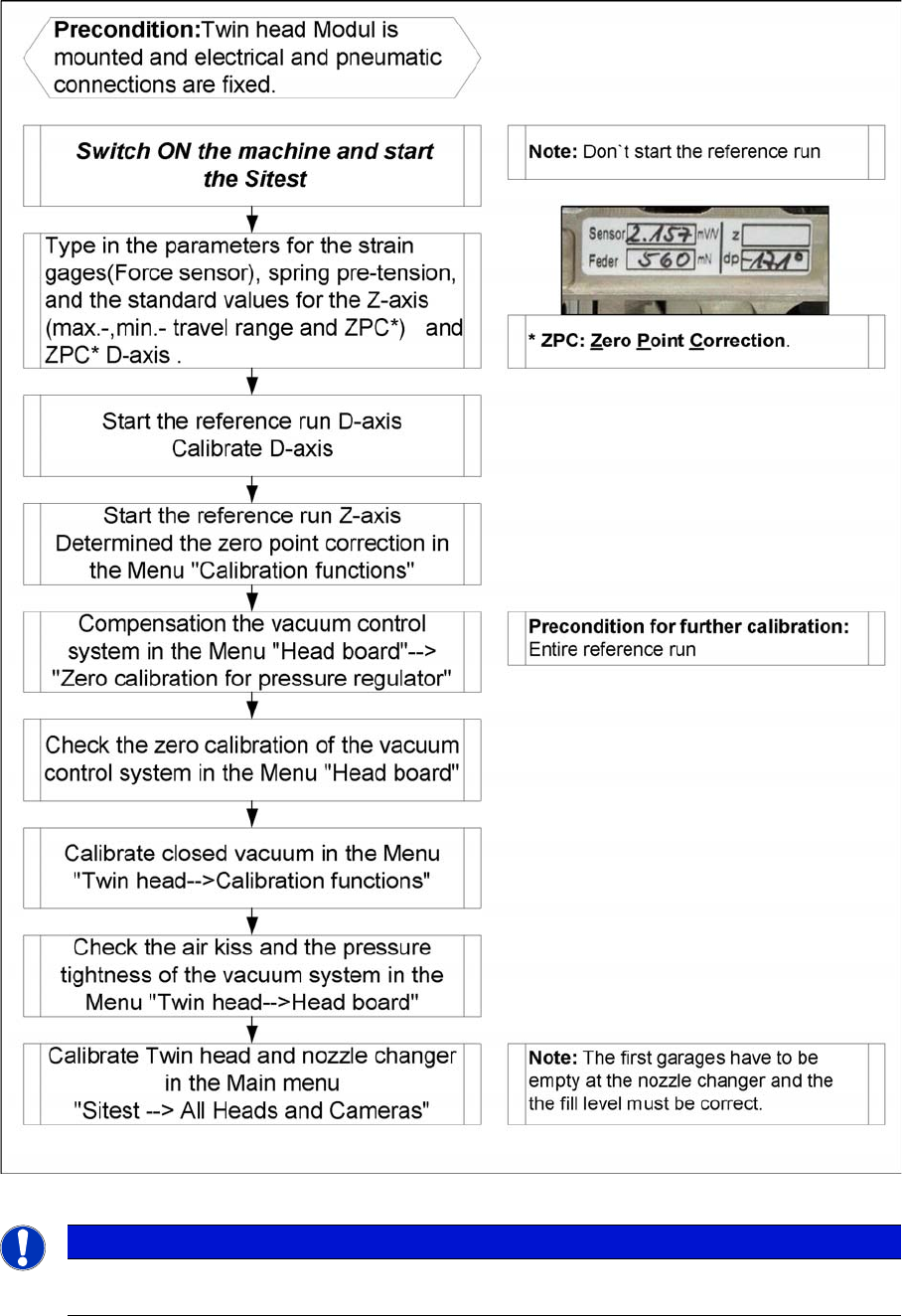
Overview calibration steps and parameter
NOTICE
This steps are necessary during the first initial setup or a replacement of the TwinHead module.
The detail description are explained on the following pages.
Settings
Pick&Place Head 6.6.4 P&P Head Parameters
248 Service Manual SIPLACE D1/D1i/D2/D2i
6.6.4
6.6.4 P&P Head Parameters
P&P Head Parameters
Parameter force sensor and spring pre-tension
SITEST:
► Select P&P module
► Select Axis functions
► Select the checkbox Z axis.
► Select the Parameter... menu and enter the values
Force sensor comparative value in [mV/V]. This value is always smaller than 3.0 [mV/V].
and Spring pretension in [mN]. (this value is between 300 and 700 [mN]).
If the values are not entered according to the data on the P&P head in SITEST, determination of the
placement force will not be correct between the 1 and 15 N.
Zero point correction (ZPC) D axis
SITEST:
► Select P&P module
► Select Axis functions
► Select the checkbox D axis
► Select Positions...
► Disable the checkbox Use digit unit.
► Mark the required line and select Edit.
► Enter the relevant ZPC value in 1/100 degrees and select Accept.
► Confirm your entry with Accept.
► Perform a reference run for the D axis.
► Do not forget to perform D axis calibration afterwards.
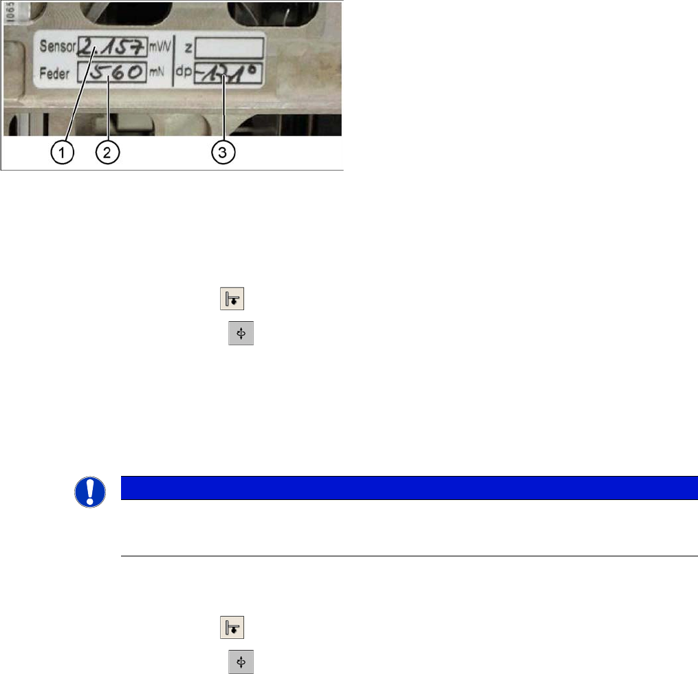
Label with D axis correction value and parameters for
P&P head
Legend
Each P&P head has a label with corrective values, which
needs to be entered after initial operation or after replac-
ing the head in SITEST.
1. Sensor (parameter for the DMS strips)
2. Spring (spring pre-tension)
3. DP (zero point correction D axis)
NOTICE
DO NOT adjust the setting screw (fine thread) for the spring pre-tension! It is currently not pos-
sible to measure the spring pretension at the customer site, meaning that the placement head
needs to be replaced.