00195376-05_SM_D1_D1i_D2_D2i_EN.pdf - 第249页
Settings 6.6.5 Calibrating the D Axis Pick&Place Head Service Manual SIPLACE D1/D1i/D2/D2i 249 Zero point correction (ZPC) Z axis SITEST: ► Select P&P module ► Select Axis functions ► Enable Z axis ► Select Posit…
Settings
Pick&Place Head 6.6.4 P&P Head Parameters
248 Service Manual SIPLACE D1/D1i/D2/D2i
6.6.4
6.6.4 P&P Head Parameters
P&P Head Parameters
Parameter force sensor and spring pre-tension
SITEST:
► Select P&P module
► Select Axis functions
► Select the checkbox Z axis.
► Select the Parameter... menu and enter the values
Force sensor comparative value in [mV/V]. This value is always smaller than 3.0 [mV/V].
and Spring pretension in [mN]. (this value is between 300 and 700 [mN]).
If the values are not entered according to the data on the P&P head in SITEST, determination of the
placement force will not be correct between the 1 and 15 N.
Zero point correction (ZPC) D axis
SITEST:
► Select P&P module
► Select Axis functions
► Select the checkbox D axis
► Select Positions...
► Disable the checkbox Use digit unit.
► Mark the required line and select Edit.
► Enter the relevant ZPC value in 1/100 degrees and select Accept.
► Confirm your entry with Accept.
► Perform a reference run for the D axis.
► Do not forget to perform D axis calibration afterwards.
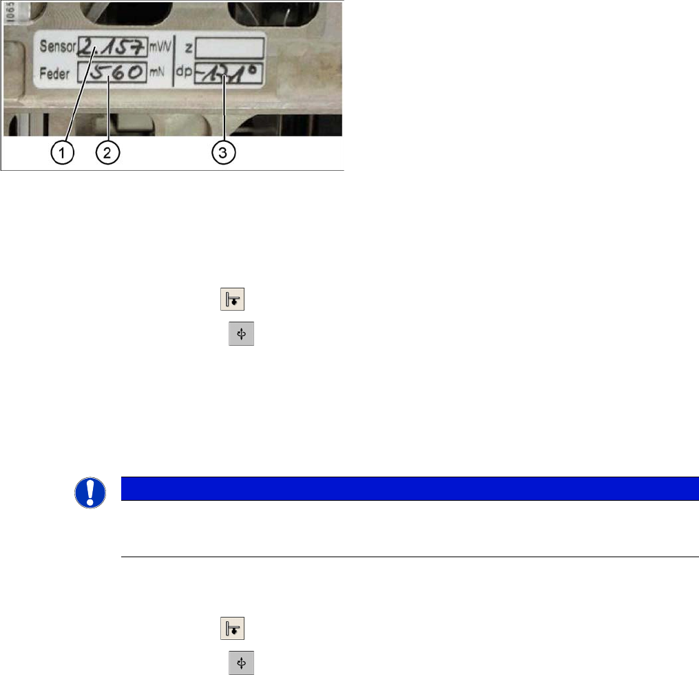
Label with D axis correction value and parameters for
P&P head
Legend
Each P&P head has a label with corrective values, which
needs to be entered after initial operation or after replac-
ing the head in SITEST.
1. Sensor (parameter for the DMS strips)
2. Spring (spring pre-tension)
3. DP (zero point correction D axis)
NOTICE
DO NOT adjust the setting screw (fine thread) for the spring pre-tension! It is currently not pos-
sible to measure the spring pretension at the customer site, meaning that the placement head
needs to be replaced.
Settings
6.6.5 Calibrating the D Axis Pick&Place Head
Service Manual SIPLACE D1/D1i/D2/D2i 249
Zero point correction (ZPC) Z axis
SITEST:
► Select P&P module
► Select Axis functions
► Enable Z axis
► Select Positions... and enter the following values:
(switch off display in digits)
⇨ max. travel range (position): 57500 µm
⇨ max. travel range (position): -2000 µm
⇨ Zero point correction: 0 µm
► ==> Perform a head height calibration (ZPC for the Z axis).
► Calibrate the head height of the P&P head. Switch over to the Calibrate Head.
6.6.5
6.6.5 Calibrating the D Axis
Calibrating the D Axis
► Put the calibration nozzle for the TWIN Head/P&P head manually at the P&P head sleeve. Make
sure that the two adjust pins engage properly in the nozzle.
► Perform an axis reference run for the D axis.
► Now check the alignment of the nozzle:
The drilling on the calibration nozzle must point to the center (SW 505 or higher) of the machine (for
SR/MC 504.0x to machine outside) and the nozzle must be aligned parallel to the PCB conveyor.
► Assign the nozzle "516" for the P&P head to be calibrated:
SITEST:
► Select P&P module
► Select the nozzle changer head function.
► Select the appropriate "segment" from the list.
► Select Edit ==> mark "516" and select Accept.
► Enable Select Segment.
► Select Confirm Exchange.
NOTICE
Only enter the standard values for the Z axis if the reference run or the calibration of the head
height was not successful.
NOTICE
Make sure that the 517 nozzle is on the P&P head.
NOTICE
The zero point correction, max- and min. travel range of the Z axis is determined when you cal-
ibrate the head height.
NOTICE
The exact zero point correction (ZPC) of the D axis is automatically calibrated on the SIPLACE
HF/HF3 with a calibration nozzle.
Correct calibration can only be expected if the ZPC angle differs less than +/- 5 degrees from
the real value.
Settings
Pick&Place Head 6.6.5 Calibrating the D Axis
250 Service Manual SIPLACE D1/D1i/D2/D2i
SITEST:
► Select P&P module
► Select Calibration Functions
► Open the Calibrate Zero Point DP Axis menu.
► When requested to do so by the SW, connect the D axis calibration nozzle.
The ZPC will be automatically determined through the angle recognition of the nozzle outline.
Repeat this procedure until the new value does not deviate more than +/- 0.01° from the previous
value.
See also
6.6.5.1 Manual Calculation of the D Axis Zero Point Correction [➙ 250]
6.6.5.1
6.6.5.1 Manual Calculation of the D Axis Zero Point Correction
Manual Calculation of the D Axis Zero Point Correction
SITEST:
► Select P&P module.
► Select Axis functions.
► Select the checkbox D-Axis.
► Select Positions...
► Set the zero point correction to 0.
► Perform an axis reference run for the D axis.
► Put the calibration nozzle for the TWIN Head/P&P head manually at the P&P head sleeve. Make
sure that the two adjust pins engage properly in the nozzle.
► Enable the D axis of the P&P head at the axis card.
► Manually rotate the nozzle into the zero position:
The drilling on the calibration nozzle must point to the center (from SW 505 onwards) of the machine
and the nozzle must be aligned parallel to the PCB conveyor.
► In order to display the position of the D axis, open the Z axis menu by checking the checkbox and
then return to D axis.
► Enter the value shown for the D axis as the zero point correction value.
► Activate the D axis of the P&P module at the axis card.
► Perform an axis reference run for the D axis.
► Now check the position of the nozzle:
The drilling on the calibration nozzle must point to the center (from SW 505 onwards) of the machine
and the nozzle must be aligned parallel to the PCB conveyor.
► Do not forget to perform D axis calibration afterwards. (see "6.6.5 Calibrating the D Axis" [ ➙ 249]).
NOTICE
If the calibration is not successful, you can roughly determine the zero point correction manually
and enter this value. (see "6.6.5.1 Manual Calculation of the D Axis Zero Point Correction"
[ ➙ 250])