00195376-05_SM_D1_D1i_D2_D2i_EN.pdf - 第253页
Settings 6.6.8 Calibrating the P&P Head Pick&Place Head Service Manual SIPLACE D1/D1i/D2/D2i 253 SITEST: 6.6.7.5 6 . 6 . 7 . 5 C h e c k in g t h e A ir B la s t Checking the Air Blast SITEST: ► Start SITEST . Mo…
Settings
Pick&Place Head 6.6.7 Calibration of Vacuum Distributor on the P&P Head
252 Service Manual SIPLACE D1/D1i/D2/D2i
6.6.7.2
6.6.7.2 Checking the Zero Calibration
Checking the Zero Calibration
SITEST:
► Select P&P module.
► Select Head Board.
► Select Measure Pressure.
The zero calibration is performed with disabled vacuum and air blast (see "6.6.7.1 Zero Calibration of
Vacuum Generator" [ ➙ 251]).
6.6.7.3
6.6.7.3 Calibrating the Closed Vacuum
Calibrating the Closed Vacuum
SITEST:
► Select P&P module.
► Select Calibration Functions.
► Select Calibrate Closed Vacuum.
6.6.7.4
6.6.7.4 Checking the Pressure Tightness of the Vacuum System
Checking the Pressure Tightness of the Vacuum System
► Start SITEST.
► Move the gantry so that you can easily reach the nozzle of the Twin Head with one and the keyboard
with the other hand.
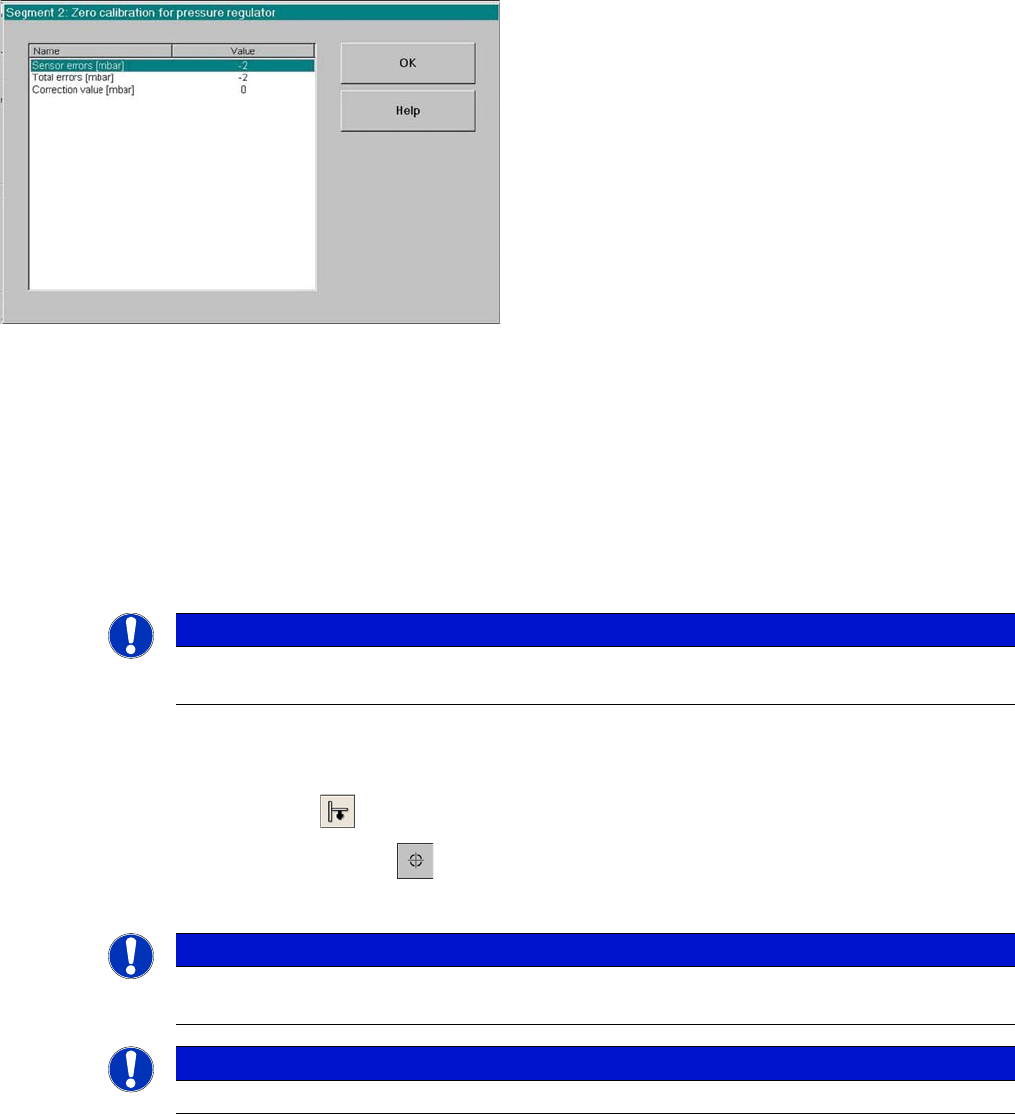
Correction values after zero calibration
► Select Zero calibration pressure regulator
The dialog box on the left shows the correction value
calculated.
► Click on OK.
The correction value will be accepted - now the reference
value equals the ambient pressure.
NOTICE
The pressure deviation to the ambient pressure at 0 - mbar (zero calibration) should not exceed
+/-10 mbar.
NOTICE
The value "Vacuum closed" is measured and stored for the P&P head.
The old and new values are shown in a dialog window.
NOTICE
The term "closed vacuum" corresponds to "threshold value closed".
Settings
6.6.8 Calibrating the P&P Head Pick&Place Head
Service Manual SIPLACE D1/D1i/D2/D2i 253
SITEST:
6.6.7.5
6.6.7.5 Checking the Air Blast
Checking the Air Blast
SITEST:
► Start SITEST. Move the gantry so that you can easily reach the nozzle of the Twin Head with one
and the keyboard with the other hand.
► Select P&P module.
► Select Head Board.
► Switch "on" the air blast.
► Close the nozzle of the appropriate P&P head (e.g. by sealing it with your finger tip).
► You can edit and modify the value for the air blast pressure or leave the standard value.
► Select Measure Pressure.
► The measured value should correspond (approx.) with the given value.
6.6.8
6.6.8 Calibrating the P&P Head
Calibrating the P&P Head
During initial setup or after replacement of a P&P head, the P&P head must be calibrated. This menu
measures the offset between the P&P module and the PCB camera center.
► Place the 517 nozzles manually on the P&P head.
► Make sure that the first nozzle garage is empty and that the component level has been adjusted ac-
cordingly in the nozzle changer. This is necessary for calibration of the pickup height.
► Enter nozzle 517 as the actual nozzle at the P&P head:
SITEST:
► Select P&P module.
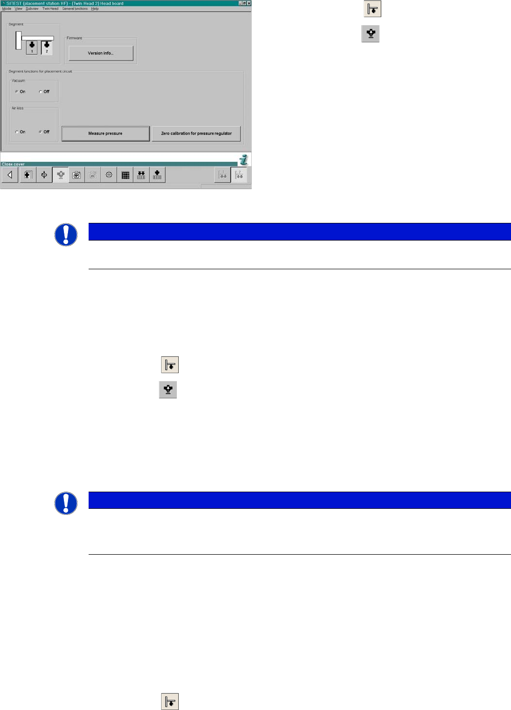
SITEST functions head board functions
► Select P&P module.
► Select Head Board.
► Switch "on" the vacuum and switch the air blast off.
► Close the nozzle of the appropriate P&P head (e.g.
by sealing it with your finger tip).
► Click on Measure Pressure.
► The displayed value should be close to the "Thresh-
old value closed".
NOTICE
The value "vacuum closed" is determined in the Calibrate P&P-Module ==> Calibrating the
closed vacuum menu.
NOTICE
The air blast value can be edited with to a value between 0 and 400 mbar, with the Siemens
Service password.
► Default setting: 400 mbar
Settings
Pick&Place Head 6.6.9 Mechanical Adjustment of the Z-Axis Incremental Encoder
254 Service Manual SIPLACE D1/D1i/D2/D2i
► Select the nozzle changer head function.
► Select the appropriate "segment" from the list.
► Select Edit ==> 517 and Accept.
► Enable Select Segment.
► Select Confirm Exchange.
► In the SITEST main menu, select All Heads and Cameras.
► Only select the checkbox P&P module (Twin Head) of the applicable placement area.
► Select Start.
6.6.9
6.6.9 Mechanical Adjustment of the Z-Axis Incremental Encoder
Mechanical Adjustment of the Z-Axis Incremental Encoder
6.6.10
6.6.10 Manual Lowering of Z Axis
Manual Lowering of Z Axis
The P&P head is designed for placement forces between 0.5 and 15 N. The rotary axis needs to be very
smooth-running, especially for low placement forces. Therefore, the rotary axis is not constructed for
traction forces.
NOTICE
The incremental encoder on the Z axis must be adjusted to a distance of 0.4 mm to the incre-
mental scale. Please adjust the incremental encoder parallel to the incremental scale.
After fitting, check the Z axis track signals (see Section Component Handling).
CAUTION
When manually lowering the Z-axis, the P&P head can be easily damaged!
► Manual lowering may only be performed by trained personnel!
CAUTION
Before performing manual lowering of the Z axis, make sure the Z axis has been released at
the relevant axis card.
► When releasing the Z axis, the Z axis return cylinder moves upwards.
► If the axis is not released, the return cylinder will automatically move upwards when the Z
axis is manually lowered, which could cause injuries and damage to the placement head.
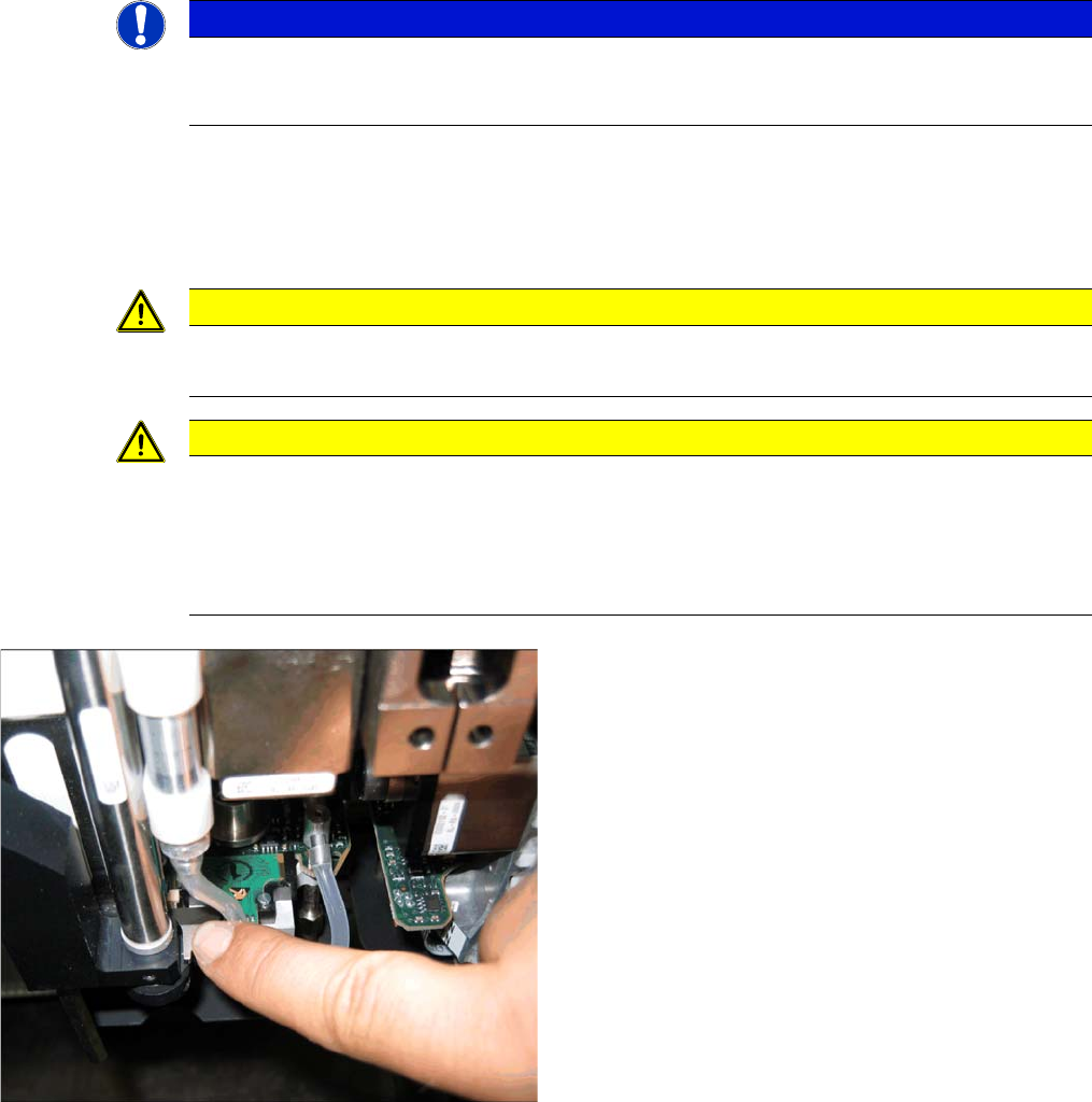
Lowering the Z-axis
► To safely press the Z axis downwards, apply manual
pressure to the marked part of the return unit driver.