00195376-05_SM_D1_D1i_D2_D2i_EN.pdf - 第255页
Settings 6.6.11 P&P Head Axis Dynamics Pick&Place Head Service Manual SIPLACE D1/D1i/D2/D2i 255 6.6.11 6 . 6 . 1 1 P & P H e a d A x is D y n a m ic s P&P Head Axis Dynamics ▪ Due to the wide component sp…
Settings
Pick&Place Head 6.6.9 Mechanical Adjustment of the Z-Axis Incremental Encoder
254 Service Manual SIPLACE D1/D1i/D2/D2i
► Select the nozzle changer head function.
► Select the appropriate "segment" from the list.
► Select Edit ==> 517 and Accept.
► Enable Select Segment.
► Select Confirm Exchange.
► In the SITEST main menu, select All Heads and Cameras.
► Only select the checkbox P&P module (Twin Head) of the applicable placement area.
► Select Start.
6.6.9
6.6.9 Mechanical Adjustment of the Z-Axis Incremental Encoder
Mechanical Adjustment of the Z-Axis Incremental Encoder
6.6.10
6.6.10 Manual Lowering of Z Axis
Manual Lowering of Z Axis
The P&P head is designed for placement forces between 0.5 and 15 N. The rotary axis needs to be very
smooth-running, especially for low placement forces. Therefore, the rotary axis is not constructed for
traction forces.
NOTICE
The incremental encoder on the Z axis must be adjusted to a distance of 0.4 mm to the incre-
mental scale. Please adjust the incremental encoder parallel to the incremental scale.
After fitting, check the Z axis track signals (see Section Component Handling).
CAUTION
When manually lowering the Z-axis, the P&P head can be easily damaged!
► Manual lowering may only be performed by trained personnel!
CAUTION
Before performing manual lowering of the Z axis, make sure the Z axis has been released at
the relevant axis card.
► When releasing the Z axis, the Z axis return cylinder moves upwards.
► If the axis is not released, the return cylinder will automatically move upwards when the Z
axis is manually lowered, which could cause injuries and damage to the placement head.
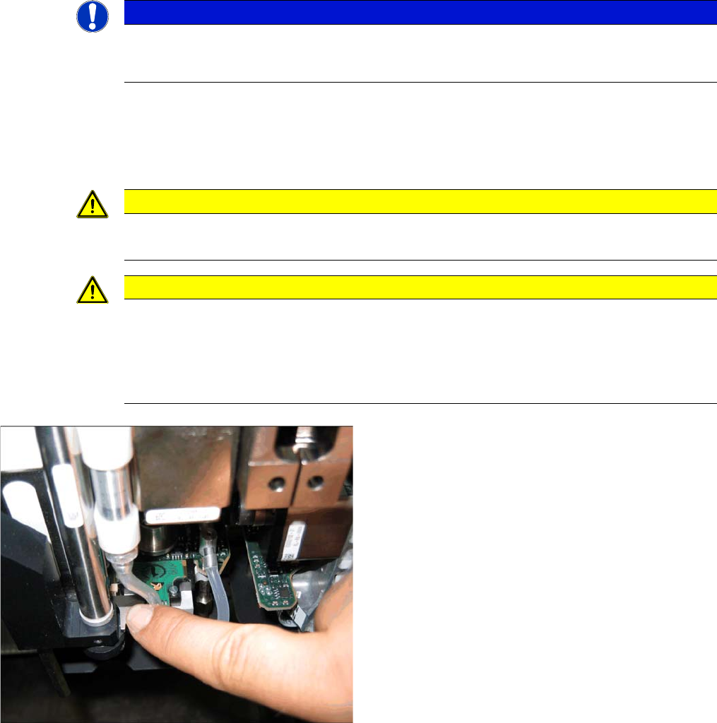
Lowering the Z-axis
► To safely press the Z axis downwards, apply manual
pressure to the marked part of the return unit driver.
Settings
6.6.11 P&P Head Axis Dynamics Pick&Place Head
Service Manual SIPLACE D1/D1i/D2/D2i 255
6.6.11
6.6.11 P&P Head Axis Dynamics
P&P Head Axis Dynamics
▪ Due to the wide component spectrum, no generally applicable oscillograms can be displayed for cor-
rect axis function.
▪ The axis dynamics can no longer be influenced by potentiometer settings.
▪ The following function descriptions should help you analyze any malfunctions which occur.
▪ The tables contain a brief description of the correct function and a description of malfunctions, their
possible causes and corresponding solution suggestions.
6.6.11.1
6.6.11.1 Z Axis
Z Axis
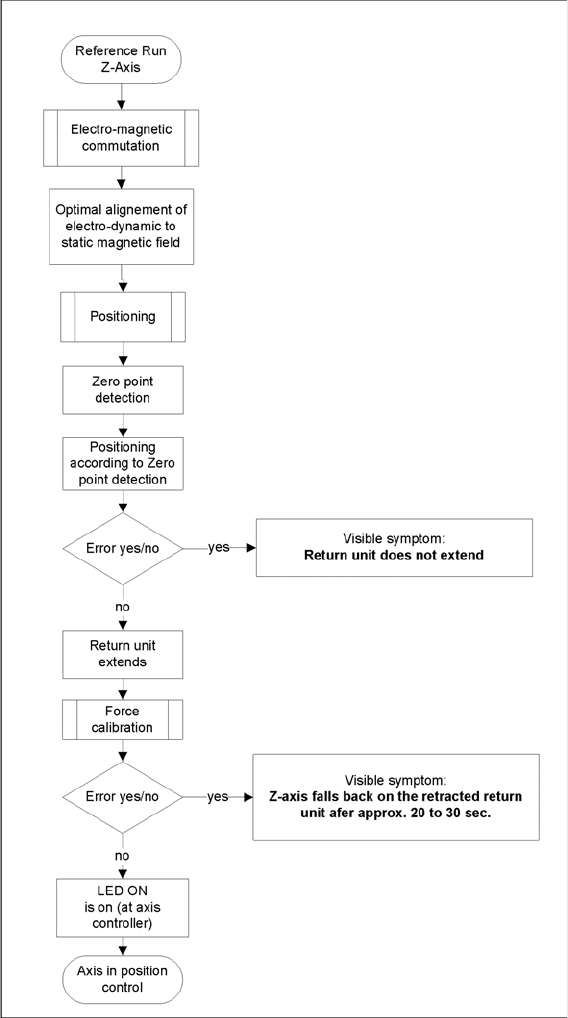
Flowchart illustrating the function of the Z-axis at the P&P head
During the Reference Run
Initial statements about the correct head function can be made from the individual procedures during the
reference run.
Z axis linear motor defect – replace the placement head.

Settings
Pick&Place Head 6.6.11 P&P Head Axis Dynamics
256 Service Manual SIPLACE D1/D1i/D2/D2i
Force measurement board defect – replace the placement head, due to the mechanical and electrical
calibration procedures required with special equipment.
During Nozzle Changeover
Function errors during nozzle changeover are not based on head axis function errors.
Detailed function: > Description > Result Malfunction: > Description > Cause/Solution
Axis reference run:
1. Search for phase current commutation
2. Zero point search
3. Position to calculated ZPC target position
Result:
Servo-controlled Z axis is referenced.
Next step: force measurement board comparison.
Z axis unable to reach target position.
FM axis not correctly initialized.
Return cylinder does not move out.
Solution:
Remove mechanical stiffness (due to transport
locks) or replace head.
Force calibration:
Automatic calibration of force measurement board
during initialization.
Result:
Return cylinder moves out (downwards).
Force measurement calibration fails.
Return cylinder does not move out. Z axis falls
down to position of return cylinder, after 20-30 sec-
onds.
Cause Force measurement board defect.
Solution: Replace head
Height reference run
Test nozzle length at conveyor edge:
Z axis tests nozzle length with 1 N placement force
and slow approach to conveyor edge.
Travel speed is proportional to the value entered
for the spring pretension.
P&P head is moved to waiting position.
Threshold value: max. spring pretension should
not exceed 700 mN.
Height measurement fails.
Positioning ends with time-out error.
Z axis does not touch conveyor edge.
Cause Incorrect entry for spring pretension with
more than 700 mN.
If this value is correct (according to the label), re-
place the head.
Detailed function: > Description > Result Malfunction: > Description > Cause/Repair
Nozzle pickup:
Z axis travels in current sensor mode into the noz-
zle interface, to engage.
The placement force is then reduced to facilitate
rotation of the D axis.
Result:
Z axis tests nozzle length after first pickup.
Z axis unable to reach target position.
Cause
Nozzle rotated by 3° and inserted into garage at
wrong angle. X/Y position of nozzle changer (NC)
not correctly calibrated.
Solution:
Calibrate the nozzle changer.
Put down the nozzle:
Z axis travels with set force into the garage.
Rotate the nozzle to lock.
Z axis travels with set force up again.
Z axis unable to reach target position.
Cause
Garage already occupied.
Nozzle manually set at incorrect angle
X/Y position of NC not correctly calibrated