00195376-05_SM_D1_D1i_D2_D2i_EN.pdf - 第259页
Settings 6.6.12 Vision DC/DC Converter Pick&Place Head Service Manual SIPLACE D1/D1i/D2/D2i 259 During Nozzle Changeover Function errors d u ring nozzle cha ngeover are not based on head axis function e rrors. During…
Settings
Pick&Place Head 6.6.11 P&P Head Axis Dynamics
258 Service Manual SIPLACE D1/D1i/D2/D2i
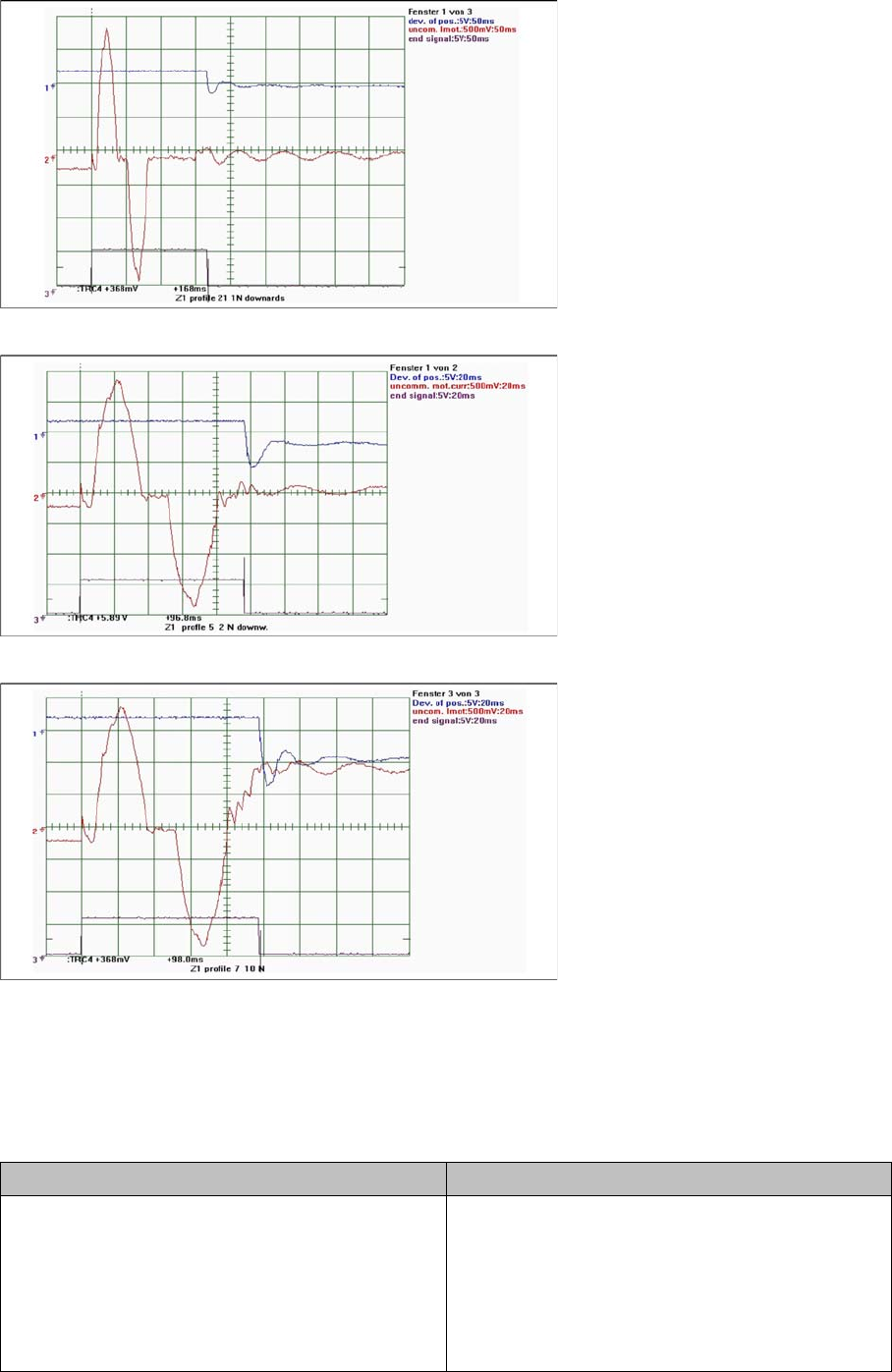
Placement with 1 N
Placement with 2 N
Placement with 10 N
6.6.11.2
6.6.11.2 D axis
D axis
During the Reference Run
Initial statements about the correct head function can be made from the individual procedures during the
reference run.
Detailed function: > Description > Result Malfunction: > Description > Cause/Repair
Axis reference run:
1. Search for phase current commutation
2. Positioning at zero point correction (ZPC) target
position:
The D axis is at 0°/180° position. Further process-
es are nozzle scanning, vacuum check and height
measurement.
D axis unable to reach target position.
Trailing cable distance error due to motor phase
failure.
Stiffness due to defect rotary part
=> replace head
Settings
6.6.12 Vision DC/DC Converter Pick&Place Head
Service Manual SIPLACE D1/D1i/D2/D2i 259
During Nozzle Changeover
Function errors during nozzle changeover are not based on head axis function errors.
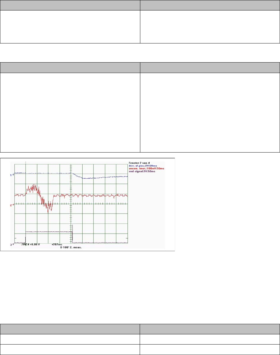
During Positioning with Travel Profiles in SITEST
D axis 180° positioning
6.6.12
6.6.12 Vision DC/DC Converter
Vision DC/DC Converter
The function of the Vision DC/DC converter is to provide the 42V voltage supply for the stationary cam-
eras.
The 42V are use for the illumination of the stationary cameras.
When replacing the Vision DC/DC converter, observe the following settings.
Bypass, wire jumper on the connector of the DC/DC converter
Detailed function: > Description > Result Malfunction: > Description > Cause/Repair
Nozzle pickup:
D axis rotates to place down position.
The D axis rotates around the nozzle in the garage,
to lock.
D axis unable to reach target position.
Cause
X/Y position of nozzle changer not correctly cali-
brated.
Detailed function: > Description > Result Malfunction: > Description > Cause/Repair
Positioning to absolute positions:
D axis moved to programmed target position. End
position signal is issued when the target corridor is
reached.
Threshold value:
A 180° positioning may only take max. 230 ms.
Heavy (over 30 gr.) and extremely large compo-
nents may exceed this threshold.
Z axis unable to reach target position.
The axis shows an oscillating, permanent devia-
tion of position. The end position signal is not set
within the 130 ms.
Cause
Electrical defect in servo amplifier
=> replace servo amplifier.
Axis swings up due to electrical or mechanical de-
fects in head
=> replace head.
Subdistributor
Bypass 1 (wire jumper) 10 - 13
Bypass 2 (wire jumper) 11 - 12
Settings
Pick&Place Head 6.6.13 Transmitting the Head-Specific Data (from SW601)
260 Service Manual SIPLACE D1/D1i/D2/D2i
6.6.13
6.6.13 Transmitting the Head-Specific Data (from SW601)
Transmitting the Head-Specific Data (from SW601)
CAUTION
Observe the direction of transfer!
After replacing the assembly, you need to send the valid machine data at the station to the new
assembly.
As the buttons required are very near to each other, take care that you do not accidentally press
the wrong one on the touch screen!
► Make sure you press the correct arrow button. To be on the safe side, select the button with
the mouse.
(C&P20 shown as example)
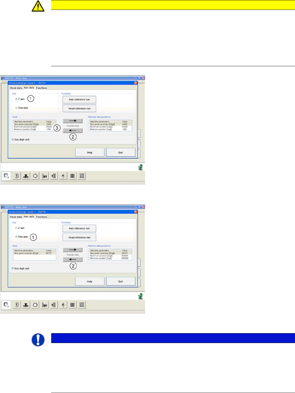
► Start SITEST and select the menu Settings: Head
Exchange: Head for the relevant head.
► Select the Axis data tab
► and enable the setting Z Axis (1).
► Transfer the machine data with the button (2) , from
the list on the right to that on the left (3).
(C&P20 shown as example)
► and enable the setting Star axis (1).
► Transfer the machine data with the button (2), from
the list on the right to that on the left.
► Select Close.
NOTICE
If you have accidentally transferred the data in the wrong direction, proceed as follows:
► Calculate the zero point correction value for the head (you may need to use the label at-
tached to the head) and enter this in SITEST.
Make sure that you use the unit "digit" for entering the data.
► Check the minimum and maximum positions and enter the values from the above screen-
shots for the C&P20.