00195376-05_SM_D1_D1i_D2_D2i_EN.pdf - 第266页
Settings Modular PCB Conveyor System 6.7.4 Checking the Limit Switch Posi tion 266 Service Manual SIPLACE D1/D1i/D2/D2i 6.7.4 6 . 7 . 4 C h e c k in g t h e L im it S w it c h P o s itio n Checking the Limit Switch Posit…
Settings
6.7.3 Moving the Fixed Conveyor Edge for ’Extra Wide Conveyor’ Modular PCB Conveyor System
Service Manual SIPLACE D1/D1i/D2/D2i 265
► Configure the new conveyor mode in SIPLACE Pro
6.7.2.3
6.7.2.3 Converting the Single Conveyor Mode Back to Flexible Dual Conveyor Mode
Converting the Single Conveyor Mode Back to Flexible Dual Conveyor Mode
► In the SITEST conveyor menu Options and Configurations, select the menu Change Widening of
Conveyor to set the default conveyor mode.
► The moveable conveyor rail of conveyor 1 (right side fixed (lane 1 left side fix)) is moved to a small
conveyor width.
► The SITEST SW requests that you disconnect the lifting tables - Do so-.
► The SITEST SW will now use the conveyor control SW to move the fixed side of conveyor 2 (right
side is fixed (lane 1 left side fixed)) back to its standard position. Check the distances between the
two fixed conveyor lanes. (see "6.7.2.1 Widening the Conveyor (Flexible Dual Conveyor for Single
Conveyor Mode)" [ ➙ 263])
► Now adjust the conveyor width of both lanes to the required values.
6.7.3
6.7.3 Moving the Fixed Conveyor Edge for ’Extra Wide Conveyor’
Moving the Fixed Conveyor Edge for ’Extra Wide Conveyor’
The standard positions of the fixed conveyor sides are preset.
► In the SITEST conveyor menu Options and Configurations and select the menu Conveyor Excess
Width, to set the conveyor mode "Extra wide".
► The fixed conveyor side of conveyor 2 (right side fixed (track 1 left side fix)) remains in its position.
► The ’fixed conveyor of track 1(right side fixed (track 2 left side fix)) is moved 34mm to the outside.
This allows you to use wider boards. The flexible conveyor side on lane 2 (lane 1 left fixed) can now
be set to accommodate boards which are wider than 216 mm (242 mm).
NOTICE
When converting the dual conveyor to a single conveyor (flexible dual conveyor, connect the
lifting tables when requested to do so by SITEST (we recommend doing this without com-
pressed air supply to the lifting table).
This function is supported by SIPLACE Pro.
NOTICE
This operating mode is possible for D machines with single or dual conveyors.
CAUTION
After the conversion process, you need to measure/calibrate the board reference corner and
the conveyor sides and then save this information in the machine data.
Settings
Modular PCB Conveyor System 6.7.4 Checking the Limit Switch Position
266 Service Manual SIPLACE D1/D1i/D2/D2i
6.7.4
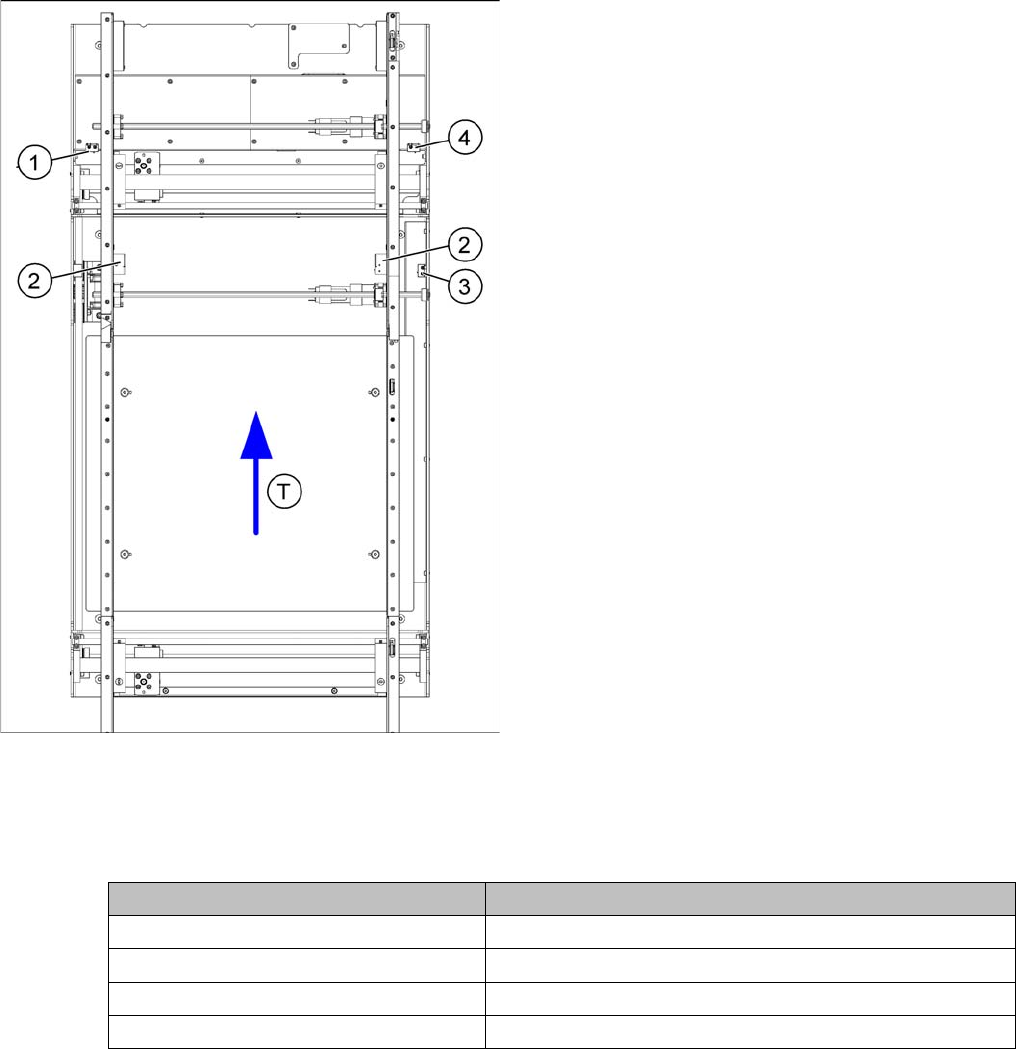
6.7.4 Checking the Limit Switch Position
Checking the Limit Switch Position
► Check the minimum and maximum width and ensure that the conveyor rails are parallel.
Values
Position of the width adjustment and conveyor side limit
switches
Legend
1. Limit switch 1 for width adjustment system of the ad-
justment unit
2. Limit switch for width adjustment system (for side)
3. Limit switch for assembly tub (for side)
4. Limit switch 2 for width adjustment system of the ad-
justment unit
▪ T = transport direction
Limit switch on the input conveyor:
There are 5 limit switches below the conveyor rails near
the input conveyor. The limit switch is designed to pre-
vent the conveyor sides hitting one another or the con-
veyor frame.
Limit switch on the output conveyor:
In the vicinity of the output conveyor there are 2 limit
switches for the adjustment unit. They protect the trave-
ling range and initialize (right side) the adjustment unit for
width adjustment.
Setup Value
Minimum width: 49.7 mm
Maximum width of single conveyor 508.5 mm
Maximum width of dual conveyor 216.5 mm (standard)
Maximum width of dual conveyor 242.5 mm (Standard)
Settings
6.7.5 Width Adjustment Unit Modular PCB Conveyor System
Service Manual SIPLACE D1/D1i/D2/D2i 267
6.7.4.1
6.7.4.1 Adjusting the Limit Switch for Initializing the Adjustment Unit
Adjusting the Limit Switch for Initializing the Adjustment Unit
6.7.5
6.7.5 Width Adjustment Unit
Width Adjustment Unit
6.7.5.1
6.7.5.1 Setting the Proximity Switch on the Adjustment Unit
Setting the Proximity Switch on the Adjustment Unit
► When installing the proximity switch (4) , make sure that the proximity switch is level with the adjust-
ment unit housing.
► The switching point is set via the actuator on the conveyor side.
► Move the adjustment unit under the conveyor side, then loosen the actuator using the screw.
► Place the driver onto the 2/10 mm end position scale, press the actuator against the end position
scale and fix with the screw.
► Check the adjustment functions for the relevant adjustment unit and correct the proximity switch po-
sition, where necessary.
► In rare cases, you may need to adjust the actuator.
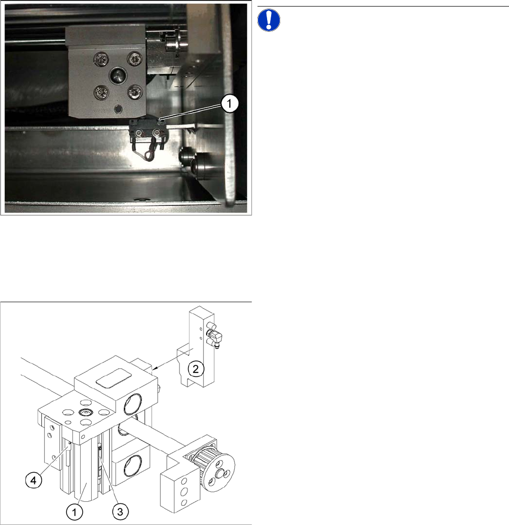
Limit /initialize switch
NOTICE! This setting is only required after re-
placing the switch or other error functions in the width ad-
justment reference run.
► Move the adjustment unit for the width adjustment by
hand (via the toothed belt) to the conveyor side.
► Loosen the two screws on the limit switch (1).
► Move the limit switch in the slot towards the adjust-
ment unit and make sure that the limit switch is safely
switched on.
► Check the switching state of the corresponding LED
(H11 for TSP 201) (H41 for TSP 301) in the conveyor
control software.
► Fit the limit switch in this position.
► Calibrate the conveyor width via the SITEST pro-
gram.
Overview of the proximity switches on the width adjust
-
ment unit
Legend
1. Short-stroke cylinder
2. Solenoid valve
3. Proximity switch for pneumatic cylinder (for "locking
pin up" recognition)
4. Proximity switch for adjustment unit(for conveyor side
recognition)
▪ The proximity switch (3) serves as a signal for con-
trolling the pneumatic valve of the adjustment unit.
Once the switching point "conveyor side present" has
been reached, the conveyor side is connected via the
pneumatic valve.