00195376-05_SM_D1_D1i_D2_D2i_EN.pdf - 第269页
Settings 6.7.6 Setting and Checking the Laser Light Barrier for the Stop per Position Modular PCB Conveyor System Service Manual SIPLACE D1/D1i/D2/D2i 269 6.7.6 6 . 7 . 6 S e t t in g a n d C h e c k in g t h e L a s e r…
Settings
Modular PCB Conveyor System 6.7.5 Width Adjustment Unit
268 Service Manual SIPLACE D1/D1i/D2/D2i
► Perform Calibrate Conveyor in SITEST.
6.7.5.2
6.7.5.2 Setting the Pneumatic Cylinder Proximity Switch on the Adjustment Unit
Setting the Pneumatic Cylinder Proximity Switch on the Adjustment Unit
► Start SITEST
► Set any conveyor width. The adjustment units are positioned directly under the conveyor side.
► Start the I/O menu.
► Activate the pneumatic cylinder.
► Set the proximity switch on the pneumatic cylinder so that the LED (H36/H37 TSP 301) (H64/65
TSP 201) shines when connected.
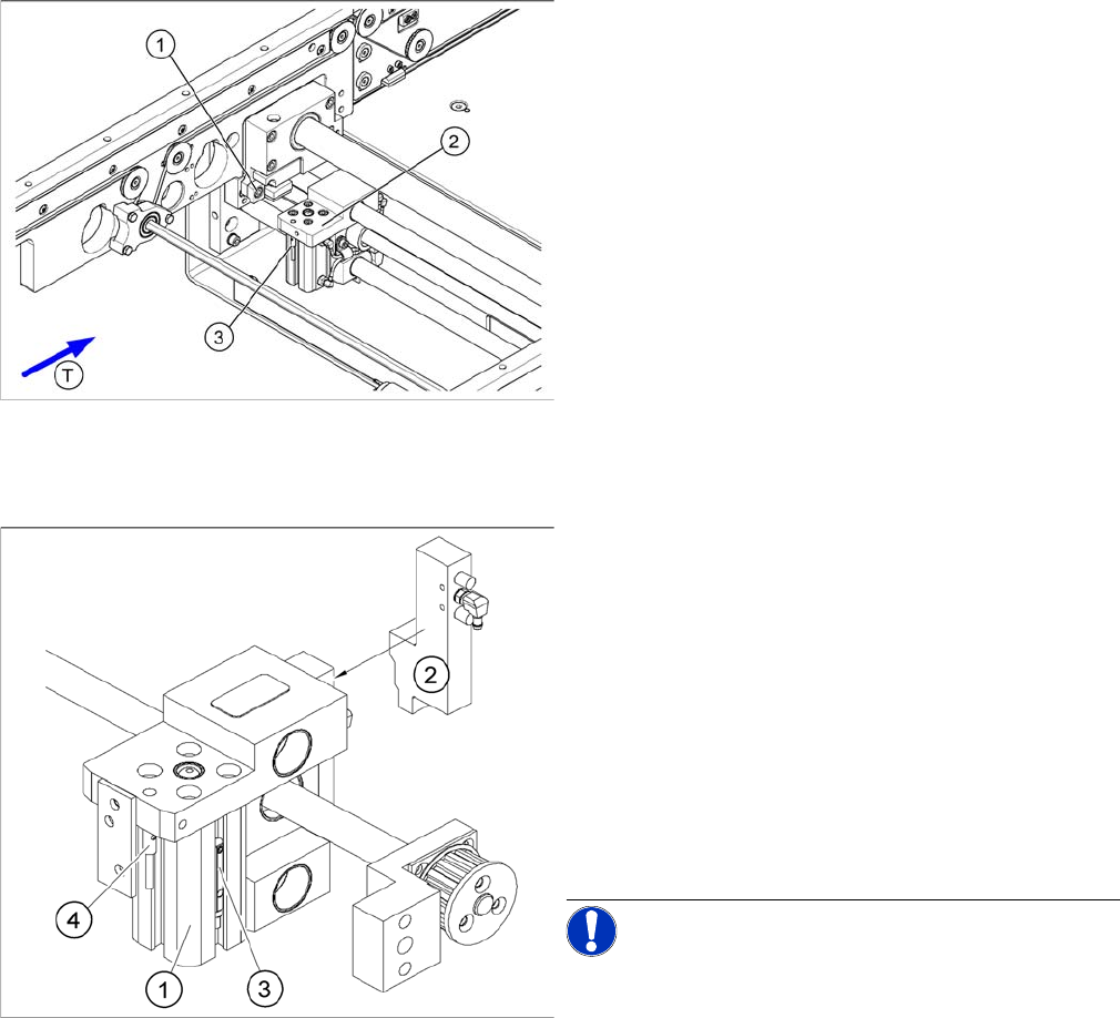
Setting the actuator block for the width adjustment
Legend
1. Fastening screw for the adjustment unit actuator
2. Adjustment unit
3. Proximity switch, adjustment unit
Overview of the proximity switches on the width adjust
-
ment unit
Legend
1. Short-stroke cylinder
2. Solenoid valve
3. Proximity switch for pneumatic cylinder (for "locking
pin up" recognition)
4. Proximity switch for adjustment unit (for conveyor
side recognition)
▪ The proximity switch (3) on the adjustment unit cylin-
der should operate when the adjustment unit pin is
pushed out by the pneumatic cylinder and therefore
connected to the conveyor side. This signal enables
the width adjustment motor.
NOTICE! The proximity switch on the pneumatic
cylinder is set in its engaged state.The proximity switch is
off when the cylinder extended into free space.
Settings
6.7.6 Setting and Checking the Laser Light Barrier for the Stopper Position Modular PCB Conveyor System
Service Manual SIPLACE D1/D1i/D2/D2i 269
6.7.6
6.7.6 Setting and Checking the Laser Light Barrier for the Stopper Position
Setting and Checking the Laser Light Barrier for the Stopper Position
Procedure
► Set the maximum conveyor width. (When using a dual conveyor, position lane 1 so that adjustments
can still be made.)
► In the station software, select General functions --> Cycle mode and switch the Safety mode on.
► Switch over to SITEST.
► Transport a PCB board with a white label on the front edge, through the placement area.
► Activate the relevant laser diode using the input/output functions in SITEST.
DANGER
Laser class 2
The laser light barrier transmitter emits class 2 laser beams. You do not need to take additional
protective measures!
► However, you should never look into the laser beam.
► Only work from the rear of the LASER diode beam (left machine side)! Keep the machine
covers on the right side closed!
NOTICE
The laser beam deflection effect is at its greatest when the conveyor is set to maximum width.
Calibration should therefore always be performed at the maximum conveyor width.
NOTICE
After setting the laser light barrier you must check or re-teach the PCB reference corner!
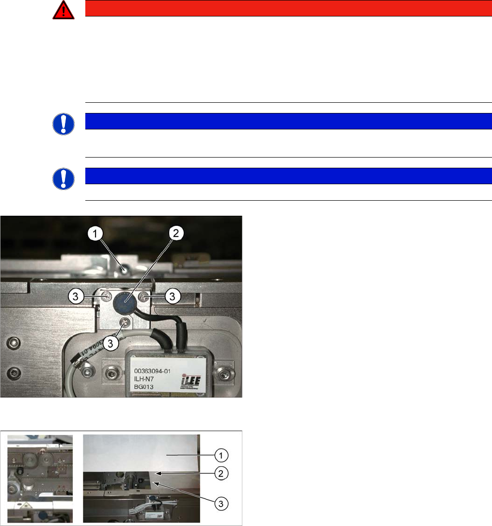
Laser light barrier
Legend
1. Laser receiver
2. Laser diode
3. Setting screws (3x)
Focussing the laser beam
Legend
1. Paper
2. Visible laser beam
3. Board parallel to laser beam
Settings
Modular PCB Conveyor System 6.7.7 Function "Constant Transport Time in Placement Area"
270 Service Manual SIPLACE D1/D1i/D2/D2i
► Only open the protective hood which is on the left, when viewed in the direction of travel, to accu-
rately set the laser light barrier.
► Check the path of the laser bean at the board, by using a white label.
► With the help of the three setting screws, adjust the laser beam to the center of the receiver.
► Check the PCB reference corner and reteach, if necessary.
6.7.7
6.7.7 Function "Constant Transport Time in Placement Area"
Function "Constant Transport Time in Placement Area"
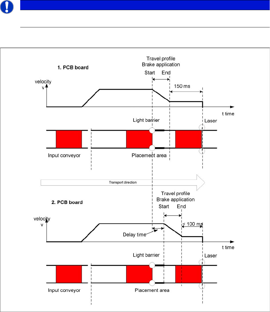
Diagrams - PCB braking
The automatic teaching at the beginning of the travel profile guarantees that the stopper is always
reached in the same time, irrespective of the board weight. The transport time remains the same.
Function of the light barrier in the placement area:
▪ Switching on the laser light barrier
▪ Starting the board braking procedure.
NOTICE
When you move the paper, the beam must follow along the edge of the PCB as accurately as
possible, with minimal deflection to the left and right.