00195376-05_SM_D1_D1i_D2_D2i_EN.pdf - 第27页
Overview 3.2.3 Power Supply Unit Electrical System Service Manual SIPLACE D1/D1i/D2/D2i 27 EMERGENCY STOP loop functions The following conditions must be fulfilled before the placement system can be s tarted or operated:…
Overview
Electrical System 3.2.3 Power Supply Unit
26 Service Manual SIPLACE D1/D1i/D2/D2i
3.2.3.3
3.2.3.3 EMERGENCY STOP Loop and Signaling Circuit
EMERGENCY STOP Loop and Signaling Circuit
Structure of the EMERGENCY STOP loop
The following contacts are connected in series and form the EMERGENCY STOP loop:
▪ Normally open (NO) contacts for the two protective cover switches
▪ Normally open (NO) contacts in the two protective switches for the cover flaps over the input and
output conveyors
▪ Normally open (NO) contacts for the two EMERGENCY STOP buttons
▪ Normally open (NO) contacts for the two component trolleys
▪ Normally open (NO) contacts for the two cover flaps (not available for D1, available as option for D2),
located above the pushbuttons and used to raise the changeover tables.
▪ Channels 1 and 2 of the protective contactor combination K1
Structure of the signaling circuit
The four signaling contacts (2x hoods, 2 x flaps) for the covers are connected in parallel and form the
"cover signal" circuit. If one or more hoods or flaps are opened, the contacts close, and the 24 V signal
is sent to the I/O module, signaling that one of the cover hoods is open.
The two signaling contacts for the EMERGENCY STOP buttons are connected in parallel and form the
"EMERGENCY STOP push-button signal circuit". When an EMERGENCY-STOP button is pressed, a
24 V signal is sent to the I/O module and signals that one of the EMERGENCY-STOP buttons has been
pressed.
The two signaling contacts for the pushbutton cover flaps (not available for D1, available as option for
D2), are connected in parallel. They form the "Flap signal" circuit. If one or more flaps are raised, a 24 V
signal is applied to the CAN bus and signals that one of the cover flaps is not closed.
The two signaling contacts for the component trolleys are connected in series and form the "Changeover
table" signal loop. If a component trolley is missing, a 0 V signal will be present at the I/O module. If all
trolleys are connected, the signal is approximately 16 V.
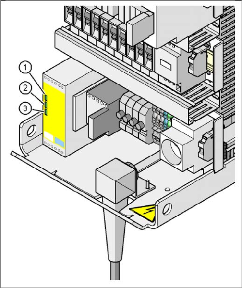
Signal LED on the protective contactor combination
Legend
1. Power
2. Channel 1
3. Channel 2
If the EMERGENCY STOP loop is closed, 24 VDC will be
present at channels 1 and 2 of the PCC. The two green
LEDs for channels 1 and 2 light up in addition to the green
Power ON LED.
Overview
3.2.3 Power Supply Unit Electrical System
Service Manual SIPLACE D1/D1i/D2/D2i 27
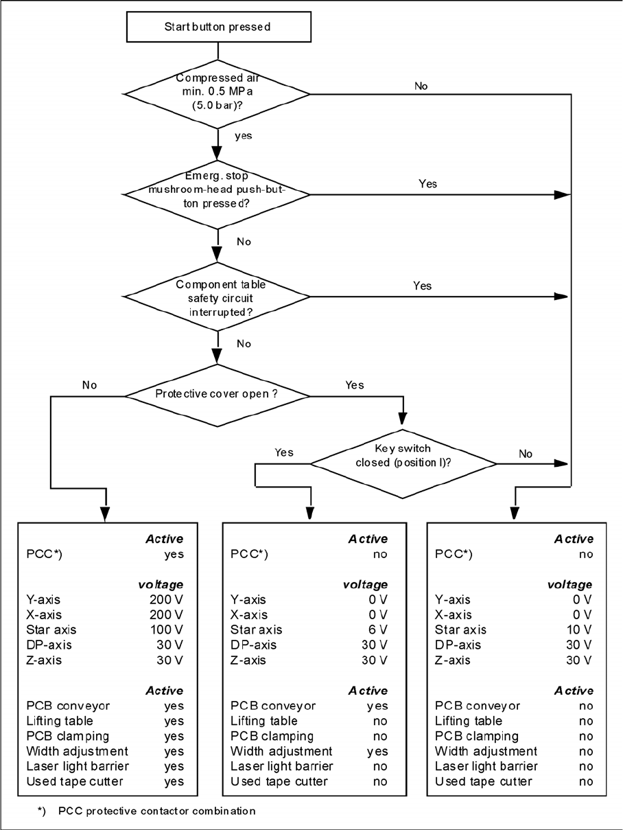
EMERGENCY STOP loop functions
The following conditions must be fulfilled before the placement system can be started or operated:
▪ All component trolleys must be docked in and connected.
▪ All protective covers must be closed.
▪ Both cover flaps over the PCB conveyor must be closed.
▪ Both emergency stop pushbuttons must be released.
▪ The emergency stop pushbutton on the WPC may need to be released.
▪ The two cover flaps (not available for D1, available as option for D2), located above the pushbuttons
and used to raise the changeover tables, must be closed.
▪ The minimum operating pressure must have been reached.
▪ The "software enable" signal must be active. This ensures that the EMERGENCY STOP loop is
closed.
▪ The power supply send 24 V to the start buttons and the protective contactor combination.
▪ If one of the start buttons is now pressed, the protective contactor combination PCC will switch and
activate the following components:
– 200 V link voltage for the servo amplifiers of the gantry axes
– 150 V link voltage for the star axes
– The axis unit will receive a "Servo Enable" signal for the servo amplifier.
– 34 V operating voltage is switched to the component trolleys.
– 24 V operating voltage is switched to the used tape cutters.
– The PCB conveyor control receives the enable signal for the PCB clamping, the PCB stopper
and the lifting table control.
The machine is then ready for use.
Overview
Electrical System 3.2.3 Power Supply Unit
28 Service Manual SIPLACE D1/D1i/D2/D2i
EMERGENCY STOP loops