00195376-05_SM_D1_D1i_D2_D2i_EN.pdf - 第271页
Settings 6.7.8 Light Barrier Functions i n Input, Intermediate an d Output Conveyors Modular PCB Conveyor System Service Manual SIPLACE D1/D1i/D2/D2i 271 The light barrier in th e placemen t area is us ed to re cognize t…
Settings
Modular PCB Conveyor System 6.7.7 Function "Constant Transport Time in Placement Area"
270 Service Manual SIPLACE D1/D1i/D2/D2i
► Only open the protective hood which is on the left, when viewed in the direction of travel, to accu-
rately set the laser light barrier.
► Check the path of the laser bean at the board, by using a white label.
► With the help of the three setting screws, adjust the laser beam to the center of the receiver.
► Check the PCB reference corner and reteach, if necessary.
6.7.7
6.7.7 Function "Constant Transport Time in Placement Area"
Function "Constant Transport Time in Placement Area"
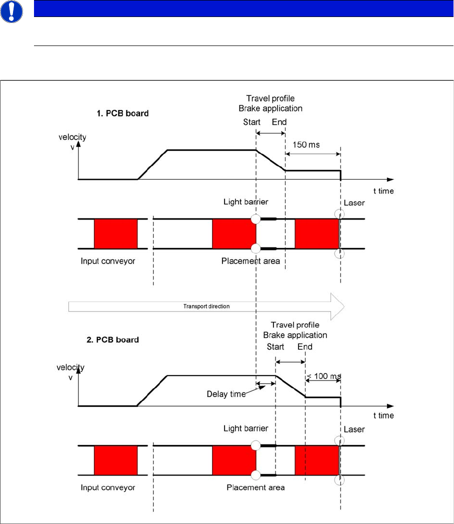
Diagrams - PCB braking
The automatic teaching at the beginning of the travel profile guarantees that the stopper is always
reached in the same time, irrespective of the board weight. The transport time remains the same.
Function of the light barrier in the placement area:
▪ Switching on the laser light barrier
▪ Starting the board braking procedure.
NOTICE
When you move the paper, the beam must follow along the edge of the PCB as accurately as
possible, with minimal deflection to the left and right.
Settings
6.7.8 Light Barrier Functions in Input, Intermediate and Output Conveyors Modular PCB Conveyor System
Service Manual SIPLACE D1/D1i/D2/D2i 271
The light barrier in the placement area is used to recognize the board and then start the braking proce-
dure (travel profile) via the conveyor control software. The software automatically "teaches" the first
board how to move in slow approach mode. Once the travel profile for braking the PCB has begun (on
time), the PCB will be reliably stopped at the laser light barrier, after a maximum of 100ms.
6.7.8
6.7.8 Light Barrier Functions in Input, Intermediate and Output Conveyors
Light Barrier Functions in Input, Intermediate and Output Conveyors
▪ Recognizing and stopping the PCB boards.
▪ Monitoring the boards in the input conveyor i.e.
If a board is recognized in the input conveyor, it will appear on the operating interface and the ma-
chine will lock the conveyor interface to the previous station. When using boards with outbreaks, the
board may stop although the signal of the light barrier is disabled and the interface to the previous
station is opened again. Then the next PCB would move into the input conveyer with the PCB still
lying in the input conveyer. The board monitoring function moves the board backwards and then
transports it forwards again, until the light barrier switches.
6.7.9
6.7.9 Setting the Clamping Actuator
Setting the Clamping Actuator
6.7.10
6.7.10 PCB Clamping Check
PCB Clamping Check
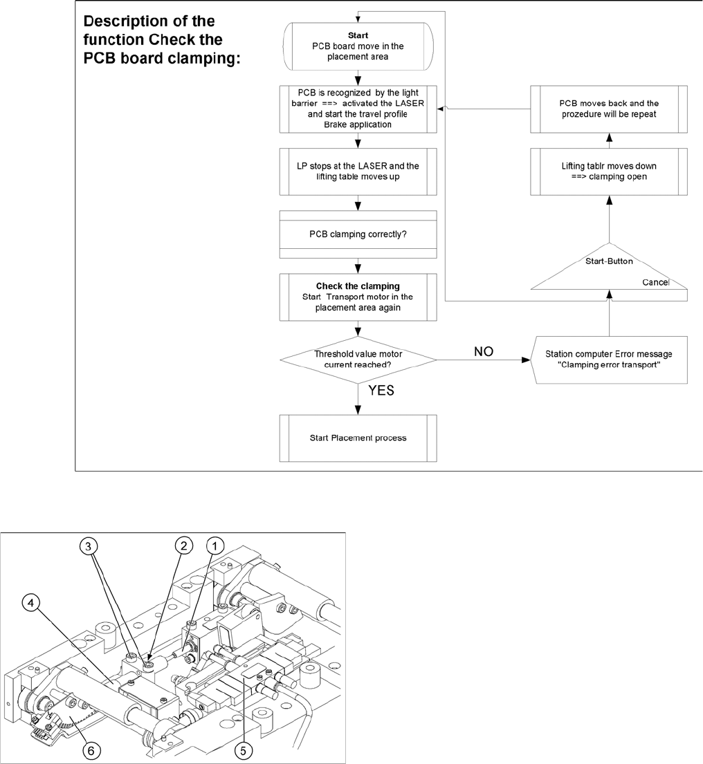
Function description:
▪ The PCB moves into the placement area, it is recognized by the light barrier, stops at the laser and
the lifting table moves up.
▪ Check PCB clamping: The conveyor motor in the placement area will restart. If the PCB is clamped
correctly the motor current will rise up and exceed a defined threshold value. Once the board has
been correctly clamped into place, the placement process will begin.
▪ If this threshold is not reached, the system assumes that the board is on its way to the intermediate
or output conveyor and has therefore not been correctly clamped into place.
▪ The station computer will issue the message "PCB not correctly clamped PA1 (PA2)". The process
can be repeated by pressing the "start button".
▪ The lifting table will move downwards, the board will be transported back and the stopper position
will be approached again.
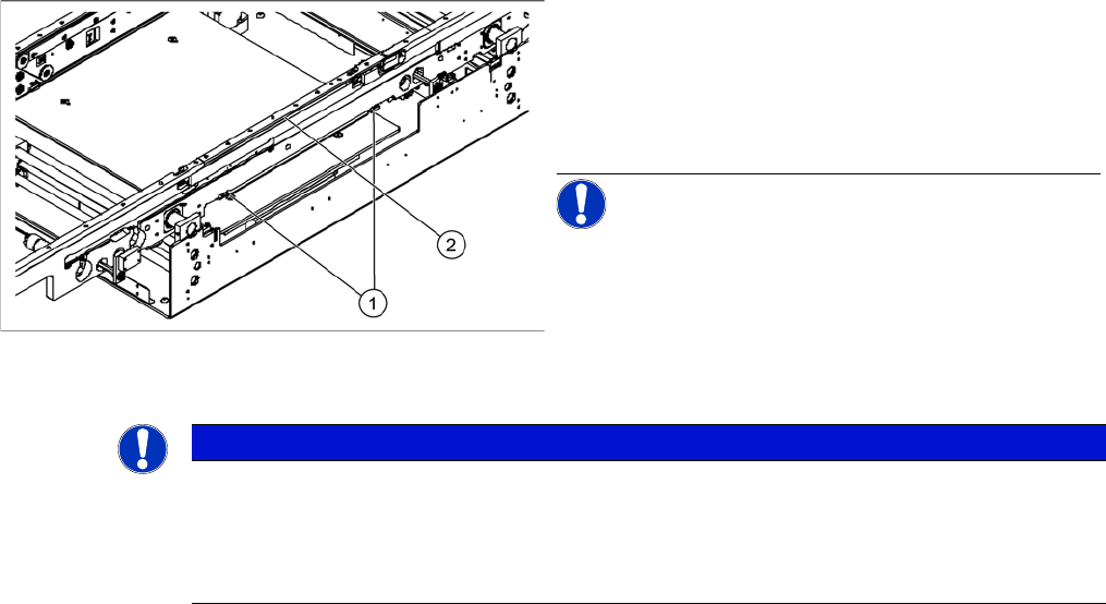
Legend
1. Actuator
2. Top edge of conveyor belt
► Set the distance between the actuator and the top
edge of the conveyor belt to 94 mm.
NOTICE! The distance between the clamping
actuator (lifting table) and the top edge of the belt must
be checked at all four contact points.
NOTICE
To check whether a PCB is clamped correctly, a motor current check is performed for the con-
veyor motor in a defined period. The appropriate motor currents are then added together. To
check the function you could put a distance plate under the conveyor side, so that the lifting
table can not move to the upper position.
The check is not performed if the option "Vacuum Tooling" is installed.
Settings
Modular PCB Conveyor System 6.7.11 Lifting Table Functions
272 Service Manual SIPLACE D1/D1i/D2/D2i
6.7.11
6.7.11 Lifting Table Functions
Lifting Table Functions
Lifting table up function
Requirements for detecting that the lifting table is up:
▪ 7-8 increments on the incremental encoder
▪ Check performed by software (see "6.7.10 PCB Clamping Check" [ ➙ 271])
▪ Dynamic response of approx. 500 ms
Lifting table down function
Requirements for detecting that the lifting table is down:
▪ 7-8 increments on the incremental encoder
Lifting table unit
Legend
1. Actuator
2. Lock nut damper
3. Fastening screws for mounting block
4. Damping unit
5. 3/5 way solenoid valve mounted on lifting table drive
cylinder
6. Fork-type light barriers / incremental disk