00195376-05_SM_D1_D1i_D2_D2i_EN.pdf - 第279页
a c p a g e
Settings
Pneumatic Cutter 6.9.1 Jumper setting on the control unit at the tape cutter
278 Service Manual SIPLACE D1/D1i/D2/D2i
► Lift or lower the component trolley table to the required height. Make sure that the hole for the re-
quired height in the bridge (5) is level with the top hole in the vertical profile bar (3).
► Fasten the bridge (5) to the vertical profile bar (3) with the 8 hexagon socket-head screws M6x12 (4).
► Unscrew the eyebolt from the component trolley table.
6.9
6.9 Pneumatic Cutter
Pneumatic Cutter
6.9.1
6.9.1 Jumper setting on the control unit at the tape cutter
Jumper setting on the control unit at the tape cutter
The jumper for the CAN bus addressing must be set according to the corresponding location in the ma-
chine.
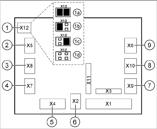
Jumper setting tape cutter
Legend - jumper SIPLACE D1/D2
1. X12 – Jumper for location code of cutter:
1a: Location 1
1b: Location 2
1c and 1d: for D1/D2 without function.
2. X5 – Voltage supply to valve (left)
3. X8 – Proximity switch for stroke cylinder out (left)
4. X7 – Proximity switch for stroke cylinder in (left)
5. X4 – CAN bus connection
6. X2 – Voltage supply for cutter +24 V and +5 V
7. X9 – Proximity switch for stroke cylinder in (left)
8. X10 – Proximity switch for stroke cylinder out (right)
9. X6 – Voltage supply to valve (right)
acpage

Item no.: 00195376-05 ASM Assembly Systems GmbH & Co. KG
Rupert-Mayer-Strasse 44
81379 München
Germany
www.siplace.com