00195376-05_SM_D1_D1i_D2_D2i_EN.pdf - 第35页
Overview 3.5.1 Back Part, Complete DLM3 Collect&Place Head Service Manual SIPLACE D1/D1i/D2/D2i 35 3.5 3 . 5 D L M 3 C o lle c t & P la c e H e a d DLM3 Collect&Place Head Overview See also 4.4 C&P6/1…
Overview
Modular PCB Conveyor System 3.3.2 Overview of Boards
34 Service Manual SIPLACE D1/D1i/D2/D2i
3.4
3.4 Modular PCB Conveyor System
Modular PCB Conveyor System
Legend
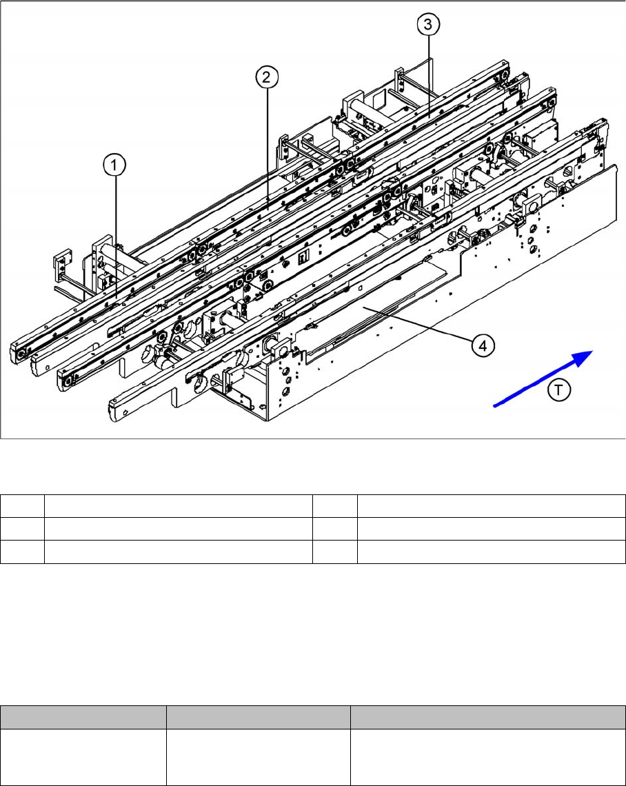
The modular conveyor system consists of an input conveyor, the conveyor in the processing area and
the output conveyor. Each conveyor system has automatic width adjustment and a lifting table to clamp
the PCB in place. The standard machine is equipped as a single PCB conveyor. A dual conveyor is avail-
able as an option. Depending on your requirements, you can choose the left or right conveyor side as a
fixed conveyor side.
Overview of Settings
1 Input conveyor 3 Output conveyor
2 Placement area 4 Lifting table in placement area
T Transport direction
Description Tools and equipment Values
Belt tensions (conveyor
belt, width adjustment)
Belt tension measuring de-
vice
See "6.7.1 Setting the Tension of the Con-
veyor Toothed Belt and the Width Adjust-
ment Unit" [ ➙ 261].
Overview
3.5.1 Back Part, Complete DLM3 Collect&Place Head
Service Manual SIPLACE D1/D1i/D2/D2i 35
3.5
3.5 DLM3 Collect&Place Head
DLM3 Collect&Place Head
Overview
See also
4.4 C&P6/12 Head [ ➙ 113]
3.5.1
3.5.1 Back Part, Complete
Back Part, Complete
Overview
▪ 6 segment DLM3 Collect&Place head (C&P6 head)
[03041229-xx]
▪ 12 segment DLM3 Collect&Place head (C&P12
head) [03041228-xx]
NOTICE! This manual does not handle the two
placement head variants separately. The structure, func-
tion and service work described apply equally to the
C&P6 and the C&P12 head.
Legend
1. Back Part, Complete
2. Star, fitted with 12 or 6 sleeves
3. Front part, complete
4. Intermediate distributor
5. Component camera
Legend
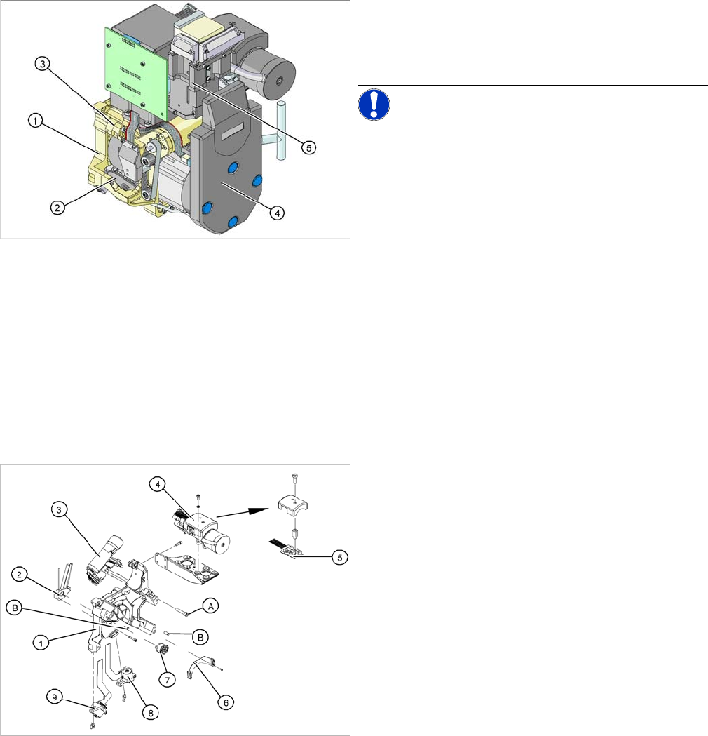
The back part of the C&P head is fixed with four hexagon
socket-head screws (A).
Two parallel pins (B) are used to center the front part of
the C&P head.
1. Back part
2. Vacuum distributor
3. Turning station
4. Vacuum generator
5. Vacuum measurement board SP6/12
6. Brake for star
7. Distributor piece
8. "Placement circuit" valve positioning drive
9. "Reject circuit" valve positioning drive
Overview
DLM3 Collect&Place Head 3.5.2 Star, Fitted
36 Service Manual SIPLACE D1/D1i/D2/D2i
3.5.2
3.5.2 Star, Fitted
Star, Fitted
Overview
3.5.3
3.5.3 Front Part, Complete
Front Part, Complete
Overview
Legend
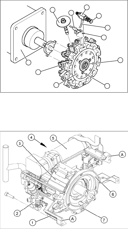
The star is fixed to the drive shaft of the star motor (B)
with three M3x8 fillister head screws (A).
1. Star
2. Distributor plate (fixed with adhesive) for distributing
the vacuum to the individual segments
3. 12 O-rings
4. 12 connection hoses
5. 12 valve plungers, complete, SP-12
6. 12 valves, SP-12
7. 12 air blast inlets
8. 12 sleeves
9. 12 segments
B
A
1
9
8
7
6
5
4
3
2
Legend
The front part is centered by two holes (A), into which the
parallel pins of the back part engage. The front is fixed to
the back part with four M4 x 16 fillister head screws.
1. Housing
2. Forced air unit
3. RSF - digital rotary encoder/ (board with safety cover)
4. Star drive, digital
5. Z axis drive
6. Raceway for the ball bearings on the 12 segments
7. Snap jaws to raise or lower the sleeves