00195376-05_SM_D1_D1i_D2_D2i_EN.pdf - 第47页
Service Work 4.1.1 Power Supply Unit Electrical System Service Manual SIPLACE D1/D1i/D2/D2i 47 Front View Power supply unit - front panel - parts overview Item Designation Voltages S1 Main switch 3LC4/3-pole/40A 3 x 204 …
Service Work
Electrical System 4.1.1 Power Supply Unit
46 Service Manual SIPLACE D1/D1i/D2/D2i
What To Do After Completing Service Work
► Fit the power supply unit and fix in place with the M8 hexagon socket-head screw.
► Make sure that you do not crush the cable when inserting the board.
► Lock the safety doors.
► Remove the key and keep in a safe place.
► Switch the placement system on at the main switch and start it up.
4.1.1.2
4.1.1.2 Measuring the Power Supply Unit
Measuring the Power Supply Unit
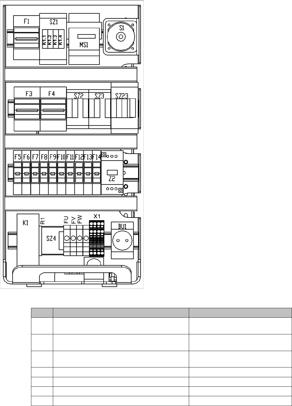
For the position of the modules, refer to "4.1.1.2.1 Front View" [ ➙ 47].
The inputs to the modules all have odd numbers and the outputs have even numbers.
In the case of fuses (F1, etc.), the input is always on the underside of the module, whereas with contac-
tors (SZ1, etc.) and motor circuit-breakers (MS1 ...), it is always at the top.
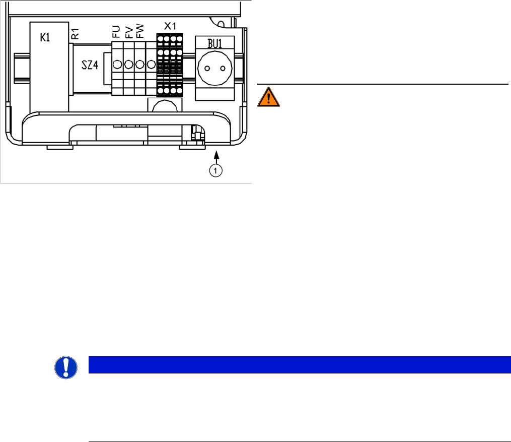
M8 hexagon socket-head screw to lock the unit
► Switch the placement system off at the main switch.
► Open the safety doors with the double-bit key.
► Loosen the M8 lock screw (1), fastening the under-
side of the unit at the front.
► Pull the unit out as far as the stop.
WARNING! Make sure that the main power ca-
ble and supply cables in the machine are not trapped and
that the insulation is not damaged.
NOTICE
The placement system must be started in order to take these measurements.
This means that the protective covers and component flaps must be closed and the changeover
tables docked. The emergency stop button must be released and the start button pressed. If
this is not the case, the operating voltages will not be switched through to the servo amplifiers,
lifting tables, etc.
Service Work
4.1.1 Power Supply Unit Electrical System
Service Manual SIPLACE D1/D1i/D2/D2i 47
Front View
Power supply unit - front panel - parts overview
Item Designation Voltages
S1 Main switch 3LC4/3-pole/40A 3 x 204 V~ / 3 x 230 V~ / 3 x 380 V~
/ 3 x 400 V~ / 3 x 415 V~
MS1 Motor circuit-breaker PKZ2/3 pin/40A 3 x 204 V~ / 3 x 230 V~ / 3 x 380 V~
/ 3 x 400 V~ / 3 x 415 V~
SZ1 Contactor 3RT10/24VDC/size S2 3 x 204 V~ / 3 x 230 V~ / 3 x 380 V~
/ 3 x 400 V~ / 3 x 415 V~
F1 Supply 24 V DC, 3 x 230V/400V AC 115 VAC / 130 VAC / 220 VAC
SZ2
SZ3
SZ23 Auxiliary contactors U,V,W for X/Y servos 3 x 140 VAC

Service Work
Electrical System 4.1.1 Power Supply Unit
48 Service Manual SIPLACE D1/D1i/D2/D2i
F4 Fuse unit - X/Y axes 3 x 200 VAC
F3 Fuse unit 230VAC for 5V power supply 3 x 220 VAC
Z2 Reactor
F14 24 V DC board conveyor and monitors 24 VDC against ground
F13 24 V DC Box PC, axis unit (fan) 24 VDC against ground
F12 24 V DC internal power supply, Micro Box PC 24 VDC against ground
F11 24 V DC sector distributor 24 VDC against ground
F10 48 V DC Vision illumination, DC/DC converter 48 VDC against ground
F9 8 V DC changeover table 8 VDC against ground
F8 40 V DC PCB handling (conveyor) 40 VDC against ground
F7 40 V DC changeover table 40 VDC against ground
F6 40 V DC/DP axes (servo card) 40 VDC against ground
F5 150V DC star axis (servo card) 150 VDC against ground
BU1 Service socket 115 / 130 / 220 / 230 / 240 VAC
X1 Feed in - terminal strip 3 x 204 V~ / 3 x 230 V~ / 3 x 380 V~
/ 3 x 400 V~ / 3 x 415 V~
FBU Fuse 6.3 AT 1 x 220 V~ against ground
FW Fuse 6.3 AT 1 x 220 V~ against ground
FV Fuse 6.3 AT 1 x 220 V~ against ground
fu Fuse 6.3 AT 1 x 220 V~ against ground
SZ4 Contactor control "ON software" 24 VDC
R1 Relay control "ON button"
K1 Protective contactor combination (PCC) 24 VDC against ground
Item Designation Voltages