00195376-05_SM_D1_D1i_D2_D2i_EN.pdf - 第50页
Service Work Electrical System 4.1.1 Power Supply Unit 50 Service Manual SIPLACE D1/D1i/D2/D2i Measuring voltages at main power filter Z1 and electrolytic cap acitor C1 The diagram a bove shows the posi tion of the power…
Service Work
4.1.1 Power Supply Unit Electrical System
Service Manual SIPLACE D1/D1i/D2/D2i 49
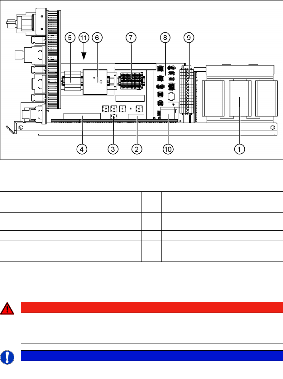
Side View
Power supply - side view - parts overview
Legend
Measuring voltages at rectifiers V1 to V8
The diagram above shows the position of rectifiers V1 to V7.
To measure rectifier V1, first remove the perspex panel.
1 T1 transformer 11.1 kVA 7 Terminal strip X1
2 V1 rectifier 8 Connector strip X2 to X10, X12, X13
3 V2, V3, V4, V6, V7 rectifier S101-B6U 160-
08
9 Secondary terminal strip with fuses (output
voltage T1)
4 Z1 mains filter - input voltage 10 Electrolytic capacitor C1
5 A2 current supply (5V/6.3A) 11 A1 power supply unit 24 V direct current
(located behind A1 and A2)
6 A3 Power fail board
DANGER
RISK OF DEATH BY ELECTRIC SHOCK
► Switch the placement system off at the main switch.
► Disconnect the placement system from the power supply.
NOTICE
The placement system must have started, otherwise there will be no AC voltage (3 x 140 VAC)
at rectifier V1.
Service Work
Electrical System 4.1.1 Power Supply Unit
50 Service Manual SIPLACE D1/D1i/D2/D2i
Measuring voltages at main power filter Z1 and electrolytic capacitor C1
The diagram above shows the position of the power supply filter and the electrolytic capacitor C1.
▪ 4 main power filters for 36 A 3-phase systems
▪ 10 electrolytic capacitors 33000 µF / 63 V
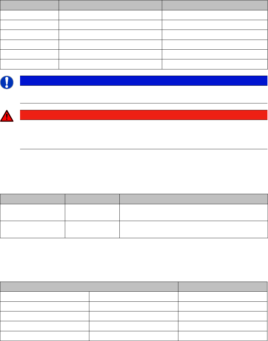
Measuring voltages at transformer T1
Primary side of transformer T1
The transformer can be connected to the following main power supplies:
3 x 230 VAC for the "on-board electrical system" is drawn at terminals 1U5, 1V5 and 1W5. These are
used to supply the PC and the monitor.
Rectifiers Input Output
V1 3 x 140 VAC 200 VDC
V2 150 VDC 150 VDC
V3 3 x 32.5 VAC 40 VDC
V4 3 x 32.5 VAC 40 VDC
V6 3 x 40.7 VAC 48 VDC
V7 3 x 24.4 VAC 24 VDC
NOTICE
► Remember to replace the perspex safety panel over rectifier V1, when the measurements
have been completed.
DANGER
RISK OF DEATH BY ELECTRIC SHOCK
► Switch the placement system off at the main switch.
► Disconnect the placement system from the power supply.
Assembly Terminal Voltages
Main power filter Z1 L1, L2, L3 3 x 204 V~ / 3 x 230 V~ / 3 x 380 V~ / 3 x 400 V~/
3x415V~
Electrolytic capacitor
C1
+ / - 52 VDC
Voltage Terminals
3 x 200-210 V~ (U.S.A) ± 5 %, 50/60 Hz 1U6, 1V6, 1W6
3 x 230 VAC ± 5 %, 50/60 Hz 1U5, 1V5, 1W5
3 x 380 VAC ± 5 %, 50/60 Hz 1U4, 1V4, 1W4
3 x 400 VAC (Europe) ± 5 %, 50/60 Hz 1U3, 1V3, 1W3
3 x 415 VAC ± 5 %, 50/60 Hz 1U1, 1V1, 1W1
Service Work
4.1.1 Power Supply Unit Electrical System
Service Manual SIPLACE D1/D1i/D2/D2i 51
Primary terminals of transformer T1
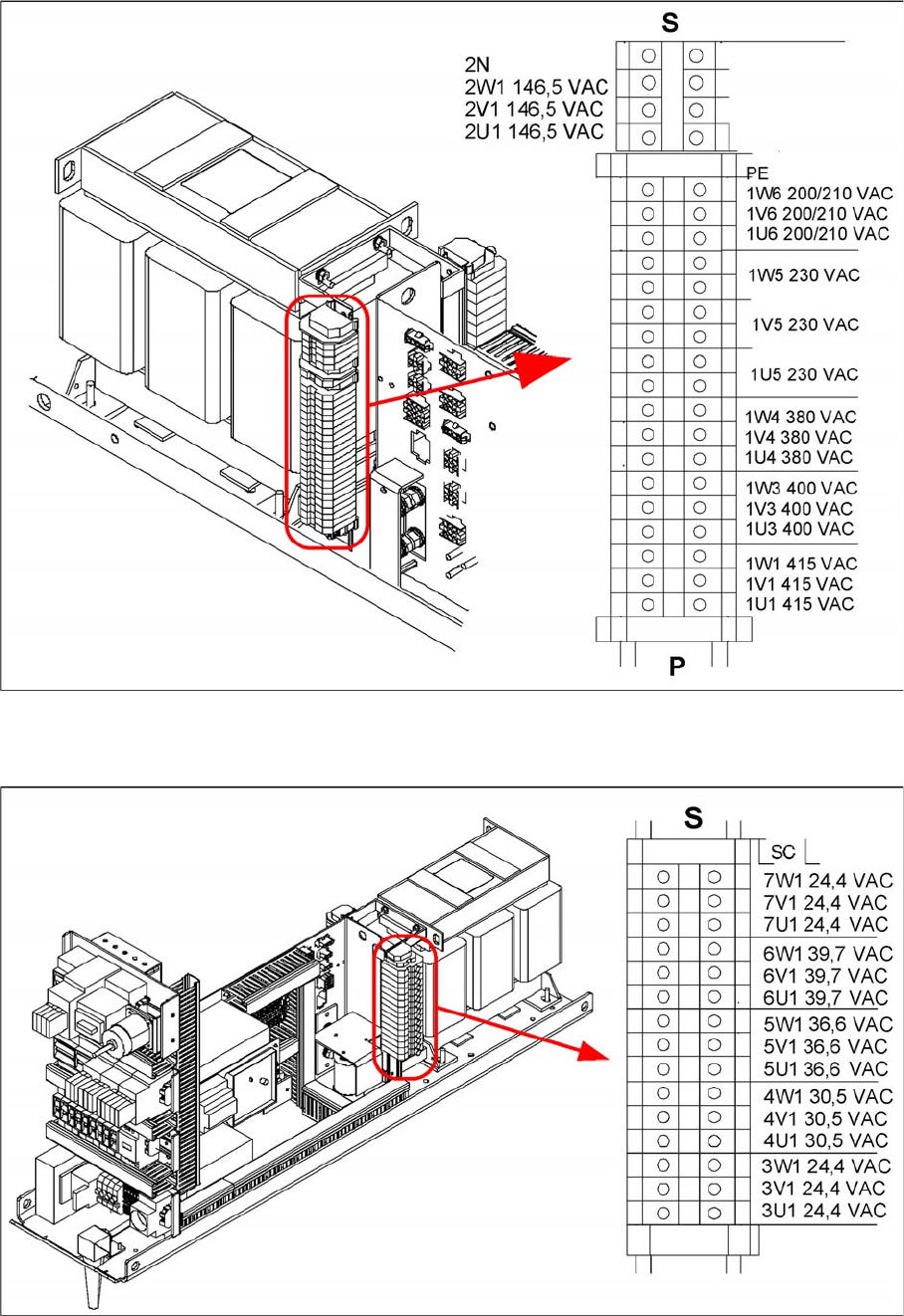
Secondary side of transformer T1
Secondary terminals of transformer T1
Transformer T1 supplies the following voltages on the secondary side:
▪ 3 x 24.4 VAC
▪ 3 x 40.7 VAC