00195376-05_SM_D1_D1i_D2_D2i_EN.pdf - 第63页
Service Work 4.2.2 Replacing the Tensioning Keys [00329478-xx] Gantries Service Manual SIPLACE D1/D1i/D2/D2i 63 Removing the tensioning keys Replacing the tensioning k eys (D4 shown as example) Legend ► Switch the machin…
Service Work
Gantries 4.2.2 Replacing the Tensioning Keys [00329478-xx]
62 Service Manual SIPLACE D1/D1i/D2/D2i
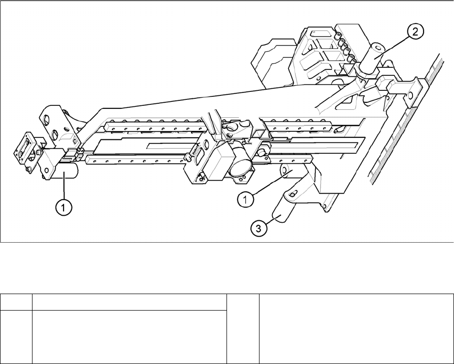
Elastomeric spring (arrangement in D4 shown)
Legend
► Loosen the M8x20 hexagon socket-head screw in the drilling in the elastomeric spring.
Installing the elastomeric spring
► Use the M8 x 20 hexagon socket-head screw to fix the elastomeric spring.
Settings
None.
4.2.2
4.2.2 Replacing the Tensioning Keys [00329478-xx]
Replacing the Tensioning Keys [00329478-xx]
Tools and equipment
▪ Set of DIN 911 Allen keys
▪ Belt tension measuring device TSM [00326015-xx]
▪ "Measuring belt tensions" operating instructions
Parts
▪ Tensioning keys [00329478-xx]
▪ Tensioning keys [03044521-xx]
1 Elastomeric spring for X-axis 3 All gantries: elastomeric spring for Y-axis
2 Gantries 1 and 3: elastomeric spring for the
Y-axis
Gantries 2 and 4: bracket instead of elasto-
meric spring
Service Work
4.2.2 Replacing the Tensioning Keys [00329478-xx] Gantries
Service Manual SIPLACE D1/D1i/D2/D2i 63
Removing the tensioning keys
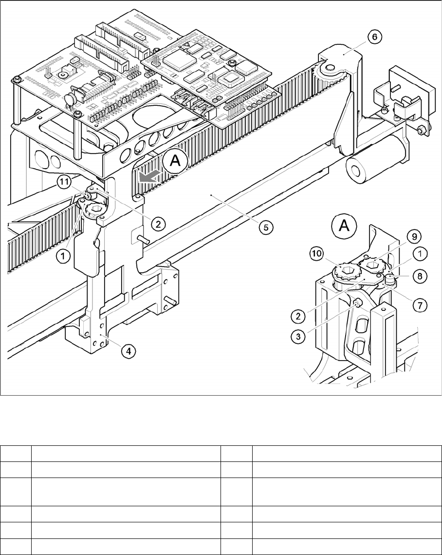
Replacing the tensioning keys (D4 shown as example)
Legend
► Switch the machine off and secure it to prevent unauthorized reactivation as described in section.
► Push the head mount in the direction of the deflection pulley (6).
► To relax the toothed belt (5), proceed as follows:
⇨ Loosen the locknut (11) and
⇨ Turn the hexagon socket-head screw (3) counterclockwise.
Removing the tensioning key, item 1 (synchronizing disk, short)
► Loosen the M4 x 5 hexagon socket-head screw (8).
1 Tensioning keys [00329478-xx] 7 Spacer bolt with Benzing U-clip
2 Tensioning keys [03044521-xx] 8 M4 x 5 hexagon socket-head screw
3 M4 x 35 hexagon socket-head screw for
tensioning the toothed belt
9 Synchronizing disk, short
4 Head mount 10 Synchronizing disk, long
5 Toothed belt for the X-axis 11 Locknut
6 Deflection pulley
Service Work
Gantries 4.2.2 Replacing the Tensioning Keys [00329478-xx]
64 Service Manual SIPLACE D1/D1i/D2/D2i
► Lift out the tensioning key.
Removing the tensioning key, item 2 (synchronizing disk, long)
► Rotate the hexagon socket-head screw (3) out of the spacer bolt (7).
► Lift out the tensioning key.
Installing the tensioning keys
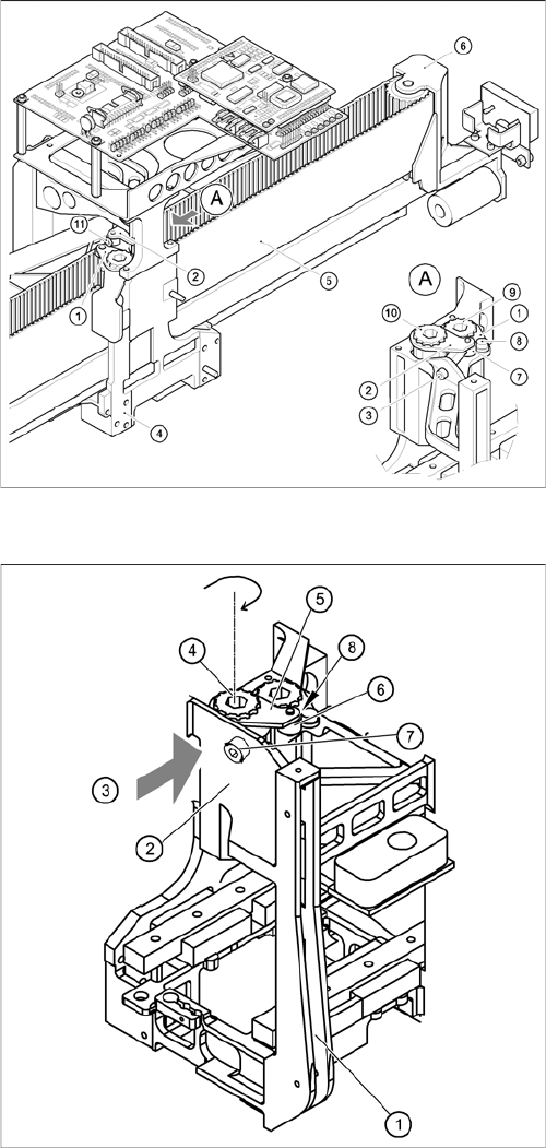
Replacing the tensioning keys (D4 shown as example)
Installing the tensioning key, item 1 (synchronizing disk,
short)
► Place the tensioning key on the "short synchronizing
disk" (9).
► Fasten the tensioning key with the M4 x 5 hexagon
socket-head screw (8).
Installing the tensioning key, item 2 (synchronizing disk,
long)
► Use the Benzing U clip to fit the spacer bolt (7) onto
the new tensioning key.
► Place the tensioning key on the "long synchronizing
disk" (10).
► Use the size 8 Allen key to turn the synchronizing disk
slightly until the hexagon socket-head screw (3) can
be screwed in.
► Pretension the toothed belt by turning the hexagon
socket-head screw clockwise.
► Insert the toothed belt. The toothed belt should run
approximately 270° around the "long synchronizing
disk" (4).