00195376-05_SM_D1_D1i_D2_D2i_EN.pdf - 第68页
Service Work Gantries 4.2.4 Replacing the X-Axis Toothed Belt [03038308-xx] 68 Service Manual SIPLACE D1/D1i/D2/D2i Settings 4.2.4 4 . 2 . 4 R e p la c in g t h e X - A x is T o o t h e d B e lt [ 0 3 0 3 8 3 0 8 - x x ]…
Service Work
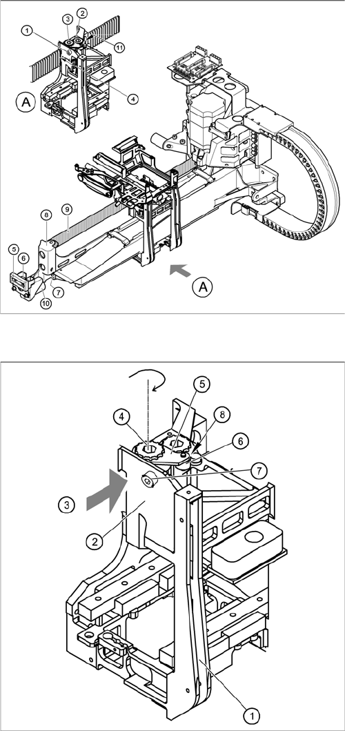
4.2.3 Replacing the Deflection Unit [03038315-xx] Gantries
Service Manual SIPLACE D1/D1i/D2/D2i 67
► Loosen the two M3 x 8 hexagon socket-head screws (6) and remove the "Y-brake outside" (5).
► Loosen the two M6 x 10 hexagon socket-head screws (7) and remove the deflection unit ’X’ (8).
► Remove the elastomeric spring (10) from the deflection unit.
Installing the deflection unit ’X’
Replacing the deflection unit (D4 shown as example)
► Fit the elastomeric spring (10) on the new deflection
unit (8).
► Fix the deflection unit (8) to the gantry, with the two
M6 x 10 hexagon socket-head screws (7).
► Align the "Y-brake outside" (5) so that it is parallel
with the braking surface and fix it to the deflection unit
(8) with the two M3 x 8 hexagon socket-head screws.
► Run the toothed belt (9) around the synchronizing
disk of the deflection unit (8).
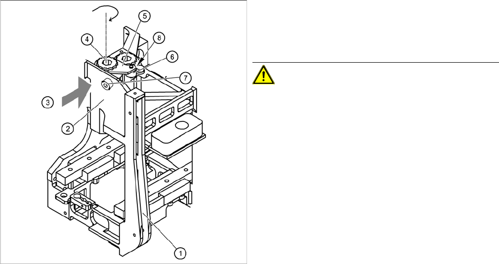
Fitting the toothed belt on the tension jack
Legend
1. Head mount
2. Tension jack for the toothed belt
3. Opening for threading the toothed belt
4. Synchronizing disk, long
5. Tensioning keys
6. Spacer bolt with M4 threaded drilling
7. M4 x 35 hexagon socket-head screw for tensioning
the toothed belt
8. Locknut
► Insert the toothed belt through the opening (3) in the
tension jack (2) until the toothed belt is run approx.
270° around the "long synchronizing disk" (4).
► Place the tensioning key (5) onto the synchronizing
disk (4).
► Use a size 8 Allen key to turn the synchronizing disk
(4) clockwise.
► Turn the hexagon socket-head screw (7) into the drill-
ing provided for the spacer bolt (6) and pretension the
X toothed belt.
Service Work
Gantries 4.2.4 Replacing the X-Axis Toothed Belt [03038308-xx]
68 Service Manual SIPLACE D1/D1i/D2/D2i
Settings
4.2.4
4.2.4 Replacing the X-Axis Toothed Belt [03038308-xx]
Replacing the X-Axis Toothed Belt [03038308-xx]
Tools and equipment
▪ Set of DIN 911 Allen keys
▪ Belt tension measuring device TSM [00326015-xx]
▪ "Measuring belt tensions" operating instructions
Parts
▪ Toothed belt, Synchroflex 50ATS5-1415 E9/11 Z+S [03038308-xx]
Fitting the toothed belt on the tension jack
► Push the head mount (1) towards the X axis motor
unit, as far as the stop on the elastomeric spring.
► Turn the hexagon socket-head screw (7) to set the
belt tension to 44 Hz +/-1 Hz.
CAUTION! Do not overstretch the toothed belt
when adjusting the belt tension.
► Secure the hexagon socket-head screw (7) with the
locknut (8).
Service Work
4.2.4 Replacing the X-Axis Toothed Belt [03038308-xx] Gantries
Service Manual SIPLACE D1/D1i/D2/D2i 69
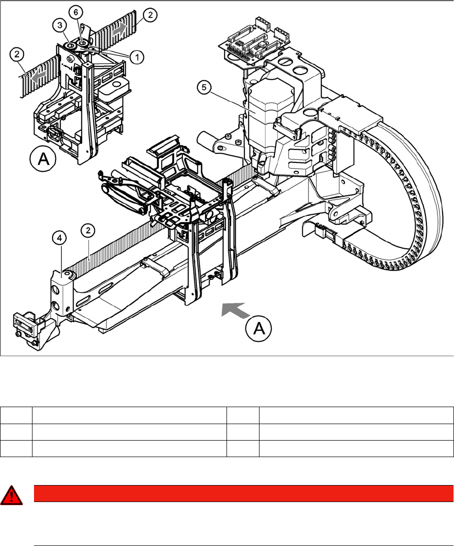
Removing the X-axis toothed belt
Removing the X toothed belt (D4 shown as example)
Legend
► Switch the machine off and secure it to prevent unauthorized reactivation as described in section.
► Remove both tensioning keys (1) (see "4.2.2 Replacing the Tensioning Keys [00329478-xx]"
[➙62]).
► Pull the toothed belt (2) off the two synchronizing disks.
► Unthread the toothed belt from the deflection unit (4).
► Pull the toothed belt off the synchronizing disk of the X motor unit (5).
1 Tensioning keys 4 Deflection unit X
2 Toothed belt 5 X-axis motor unit
3 Synchronizing disk, long 6 Synchronizing disk, short
DANGER
POWERFUL MAGNETIC FIELD
Always follow the special safety instructions when working in the vicinity of powerful magnetic
fields (see section).