00195376-05_SM_D1_D1i_D2_D2i_EN.pdf - 第73页
Service Work 4.2.5 Replacing the X Motor Unit 00333167-xx Gantries Service Manual SIPLACE D1/D1i/D2/D2i 73 Installing the X-axis motor unit ► When using SIPLACE D1 machines, t he heat sink from the old X mo tor needs to …

Service Work
Gantries 4.2.5 Replacing the X Motor Unit 00333167-xx
72 Service Manual SIPLACE D1/D1i/D2/D2i
► Switch off the machine and secure it to prevent unauthorized reactivation.
1 gantry D1 (2 gantries D2)
► Remove the cover strip on the crossbeam above the gantry concerned:
⇨ Unplug the fan cable. The fan is fixed to the cover strip.
⇨ Remove the cover strip (3 M6x8 hexagon socket-head screws).
► Cut the cable ties holding the X-axis motor cable.
► Remove the cable clamp for the flat ribbon cable (11).
► Disconnect all the plugs from the X/Y distributor (5).
► Remove the X/Y distributor (5).
► Remove the board holder for the X/Y distributor (9).
► Remove the cable holders (10) on the trailing cable.
► To relax the toothed belt (3), proceed as follows:
⇨ Loosen the locknut (8) and
⇨ Turn the hexagon socket-head screw (2) counterclockwise.
► Loosen the two M6 x 14 hexagon socket-head screws (7) fixing the X motor unit (4).
► Pull the X motor unit (4) up and out,
► at the same time pushing the board holder slightly to the side.
DANGER
POWERFUL MAGNETIC FIELD
► Always follow the special safety instructions when working in the vicinity of powerful mag-
netic fields.
Service Work
4.2.5 Replacing the X Motor Unit 00333167-xx Gantries
Service Manual SIPLACE D1/D1i/D2/D2i 73
Installing the X-axis motor unit
► When using SIPLACE D1 machines, the heat sink from the old X motor needs to be fitted onto the
new one. For details, consult the corresponding retrofitting guide [00195618-xx].
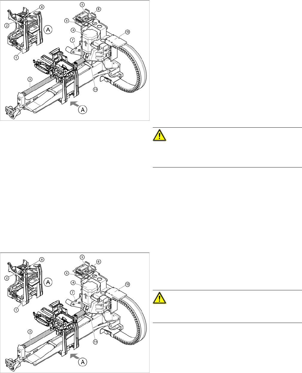
Replacing the X motor unit (D4 shown as example)
1 gantry D1 (2 gantries D2)
► Carefully insert the X motor unit (4) as far as the stop,
making sure that you do not damage the toothed belt.
The motor cable points towards the permanent mag-
nets of the linear drive.
► Fix the X motor unit into place with the two hexagon
socket-head screws (7).
► Fit the cable holders for the trailing cable (10).
► Fit the board holder (9).
► Fit the X/Y distributor (5).
► Connect all plugs to their sockets on the X/Y distribu-
tor (5).
► Fix the flat ribbon cable with the cable clamp (11).
► Fix all the cables with cable ties.
CAUTION!
Make sure that the cables are firmly seated. Otherwise,
the high acceleration forces may cause the cable to slip
out of position and shear through.
► Tension the X toothed belt with the hexagon socket-
head screw (2).
► Use the three M6 x 8 hexagon socket-head screws to
fit the cover strip to the crossbeam, above the gantry
concerned.
► Connect the cable of the fan motor to the socket.
Replacing the X motor unit (D4 shown as example)
► Push the head mount (1) towards the X axis motor
unit, as far as the stop on the elastomeric spring.
► Turn the hexagon socket-head screw (2) to set the
belt tension to 44 Hz +/-1 Hz.
CAUTION!
Do not overstretch the toothed belt when adjusting the
belt tension.
► Secure the hexagon socket-head screw (2) with the
locknut (8).
Service Work
Gantries 4.2.6 Replacing the Gantry Head Distributor [003039274-xx]
74 Service Manual SIPLACE D1/D1i/D2/D2i
4.2.6
4.2.6 Replacing the Gantry Head Distributor [003039274-xx]
Replacing the Gantry Head Distributor [003039274-xx]
Removal/Installation
4.2.7
4.2.7 Replacing the PCB Camera [03030762-xx]
Replacing the PCB Camera [03030762-xx]
Removal/Installation
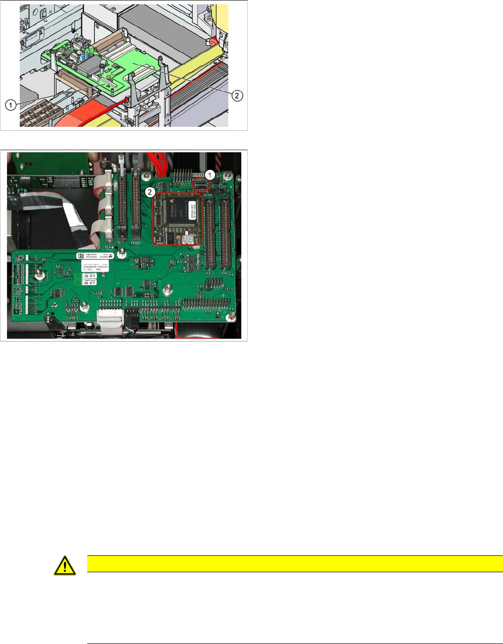
Legend
1. Vision processor subboard (Vision board D series -
total)
2. Gantry head distributor [003039274-xx]
Gantry head distributor
► Remove the Vision processor subboard from the gan-
try head distributor. (See "4.2.13 Replacing the Vi-
sion Processor Subboard [03040460-xx]" [ ➙ 80].)
► Unplug all electrical connections from the top (upper
side) of the gantry head distributor and label these for
easier reconnection, later.
► Loosen the 5 screws fastening the gantry head dis-
tributor.
► Detach all electrical connections from the bottom (un-
derside) of the gantry head distributor and label these
for easier reconnection, later.
► Remove the gantry head distributor.
► Remove the TQM module (2) from the old gantry
head distributor and fit it on the new one. You may
need to loosen a screw on the TQM module.
► Where necessary, remove the hexagon spacer bolt
from the old gantry head distributor and fit it on the
new one.
► Fit the new gantry head distributor and the Vision pro-
cessor subboard by following the instructions in re-
verse order.
► Fix the cables, so that they are not subject to vibra-
tions or shearing.
► Set the jumper S1 (1) correctly. (See "6.2.3.1.1 DIP
Switch on Gantry Head Distributor" [ ➙ 208].)
CAUTION
Do not damage the fixture clips!
To disconnect the component and PCB camera connections, you need to open the fixture clips
by applying pressure to the side of the connector.
► For details see "4.4.22 Press Fit Connections with Fixture Clips on the Vision Board (D Se-
ries)" [ ➙ 157]