00195376-05_SM_D1_D1i_D2_D2i_EN.pdf - 第75页
Service Work 4.2.8 Replacing the X-Axis In cremental Encoder (Read Head) [030 47215S-xx] Gantries Service Manual SIPLACE D1/D1i/D2/D2i 75 4.2.8 4 . 2 . 8 R e p la c in g t h e X - A x is I n c r e m e n t a l E n c o d e…
Service Work
Gantries 4.2.6 Replacing the Gantry Head Distributor [003039274-xx]
74 Service Manual SIPLACE D1/D1i/D2/D2i
4.2.6
4.2.6 Replacing the Gantry Head Distributor [003039274-xx]
Replacing the Gantry Head Distributor [003039274-xx]
Removal/Installation
4.2.7
4.2.7 Replacing the PCB Camera [03030762-xx]
Replacing the PCB Camera [03030762-xx]
Removal/Installation
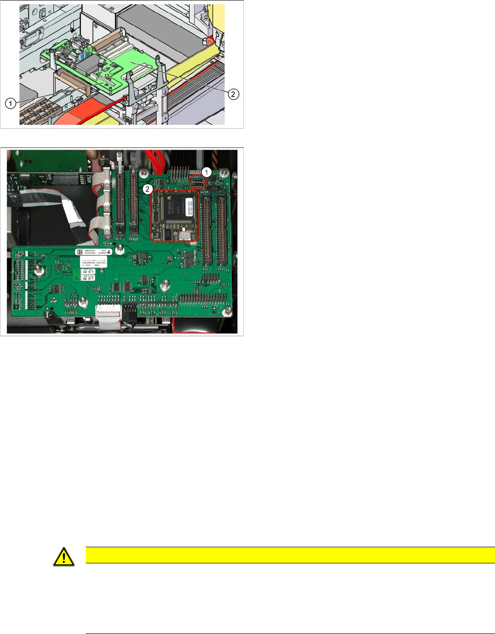
Legend
1. Vision processor subboard (Vision board D series -
total)
2. Gantry head distributor [003039274-xx]
Gantry head distributor
► Remove the Vision processor subboard from the gan-
try head distributor. (See "4.2.13 Replacing the Vi-
sion Processor Subboard [03040460-xx]" [ ➙ 80].)
► Unplug all electrical connections from the top (upper
side) of the gantry head distributor and label these for
easier reconnection, later.
► Loosen the 5 screws fastening the gantry head dis-
tributor.
► Detach all electrical connections from the bottom (un-
derside) of the gantry head distributor and label these
for easier reconnection, later.
► Remove the gantry head distributor.
► Remove the TQM module (2) from the old gantry
head distributor and fit it on the new one. You may
need to loosen a screw on the TQM module.
► Where necessary, remove the hexagon spacer bolt
from the old gantry head distributor and fit it on the
new one.
► Fit the new gantry head distributor and the Vision pro-
cessor subboard by following the instructions in re-
verse order.
► Fix the cables, so that they are not subject to vibra-
tions or shearing.
► Set the jumper S1 (1) correctly. (See "6.2.3.1.1 DIP
Switch on Gantry Head Distributor" [ ➙ 208].)
CAUTION
Do not damage the fixture clips!
To disconnect the component and PCB camera connections, you need to open the fixture clips
by applying pressure to the side of the connector.
► For details see "4.4.22 Press Fit Connections with Fixture Clips on the Vision Board (D Se-
ries)" [ ➙ 157]
Service Work
4.2.8 Replacing the X-Axis Incremental Encoder (Read Head) [03047215S-xx] Gantries
Service Manual SIPLACE D1/D1i/D2/D2i 75
4.2.8
4.2.8 Replacing the X-Axis Incremental Encoder (Read Head) [03047215S-xx]
Replacing the X-Axis Incremental Encoder (Read Head) [03047215S-xx]
Overview
► Unplug the connection cable at the gantry head dis-
tributor and unthread it as far as the PCB camera (1).
Open the cable ties, where necessary.
► Loosen the four screws fastening the PCB camera
mount (2).
► Install the new PCB camera on the mount (2). Tighten
the screws and secure with loctite 241.
► Run the connection cable to the gantry head distribu-
tor and reconnect to the electrical system.
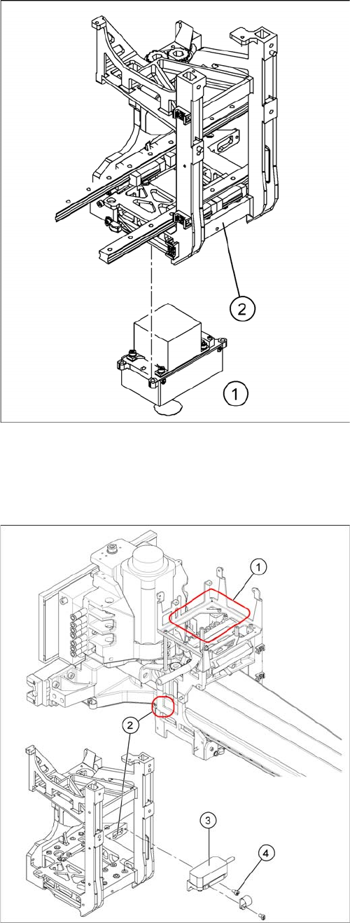
Legend
1. Installation point for gantry head distributor with Vi-
sion board
2. Incremental encoder position
3. Incremental encoder (read head)
4. M3x6 fastening screws (fixed with Loctite No. 241)
► Move the relevant changeover table out of the ma-
chine.
► Shut down the machine and switch it off.
► Unplug the incremental encoder (3) from the gantry
head distributor (1).
Service Work
Gantries 4.2.8 Replacing the X-Axis Incremental Encoder (Read Head) [03047215S-xx]
76 Service Manual SIPLACE D1/D1i/D2/D2i
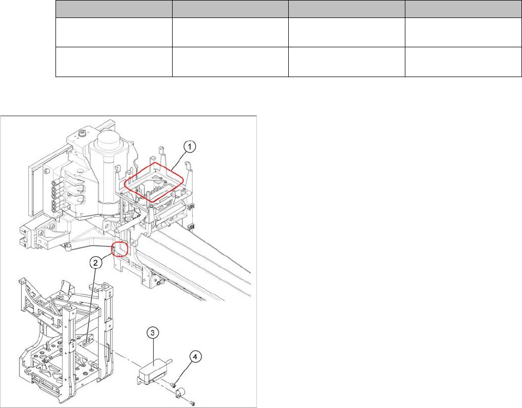
Press-fit connections
Removal
Assembly Gantry Board Terminals
X axis incremental en-
coder
Gantry 1 (C&P head ) Gantry head distributor
[03039274-xx]
X15ac
X axis incremental en-
coder
Gantry 2 (P&P head ) Gantry head distributor
[03039274-xx]
X15bc
► Unthread the connection cable as far as the incre-
mental encoder (3).
► Loosen the screws (4) fastening the incremental en-
coder (3) of the X axis and carefully lift off the incre-
mental encoder.