00195376-05_SM_D1_D1i_D2_D2i_EN.pdf - 第77页
Service Work 4.2.8 Replacing the X-Axis In cremental Encoder (Read Head) [030 47215S-xx] Gantries Service Manual SIPLACE D1/D1i/D2/D2i 77 Installation ► Clean the reading surface of the incremental encoder with a cloth a…
Service Work
Gantries 4.2.8 Replacing the X-Axis Incremental Encoder (Read Head) [03047215S-xx]
76 Service Manual SIPLACE D1/D1i/D2/D2i
Press-fit connections
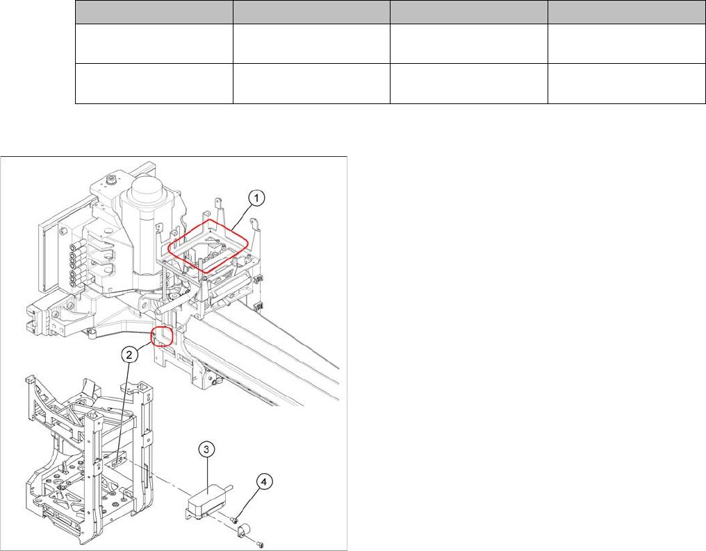
Removal
Assembly Gantry Board Terminals
X axis incremental en-
coder
Gantry 1 (C&P head ) Gantry head distributor
[03039274-xx]
X15ac
X axis incremental en-
coder
Gantry 2 (P&P head ) Gantry head distributor
[03039274-xx]
X15bc
► Unthread the connection cable as far as the incre-
mental encoder (3).
► Loosen the screws (4) fastening the incremental en-
coder (3) of the X axis and carefully lift off the incre-
mental encoder.
Service Work
4.2.8 Replacing the X-Axis Incremental Encoder (Read Head) [03047215S-xx] Gantries
Service Manual SIPLACE D1/D1i/D2/D2i 77
Installation
► Clean the reading surface of the incremental encoder
with a cloth and ethanol or with a Q-tip.
► Loosely fasten the incremental encoder (3) with the
screws (4).
► The incremental encoder must be aligned with a 0.4
mm gap to the scale. Use the corresponding thick-
ness gauge (plastic).
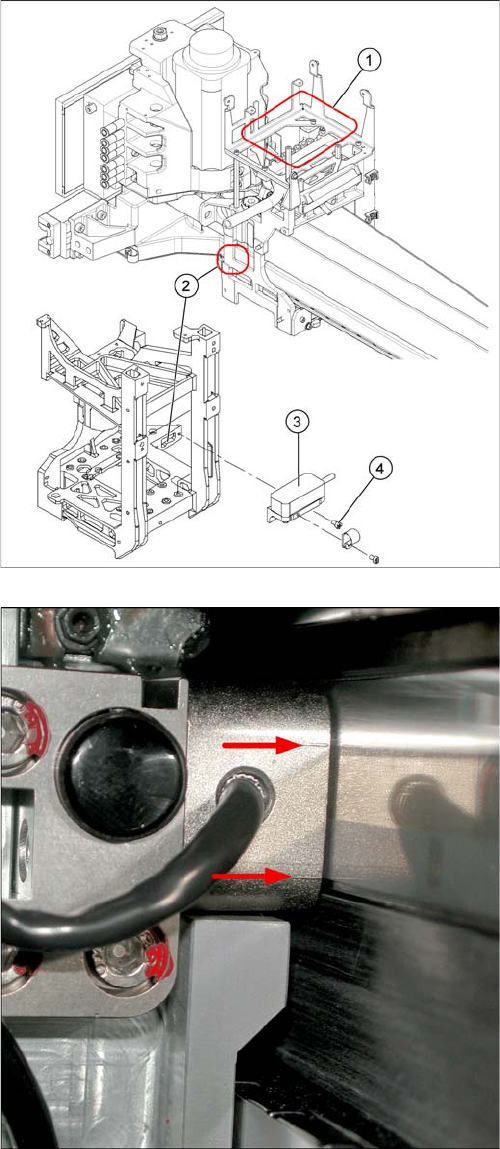
Casting marks on the incremental encoder (X-axis on X-
series machine shown as example)
► You must set the exact height to the scale.
► Align the incremental encoder, using the two casting
marks (arrows), which mark the read area.
Service Work
Gantries 4.2.9 Replacing the Y-Axis Incremental Encoder (Read Head) [03047216S-xx]
78 Service Manual SIPLACE D1/D1i/D2/D2i
Installation
4.2.9
4.2.9 Replacing the Y-Axis Incremental Encoder (Read Head) [03047216S-xx]
Replacing the Y-Axis Incremental Encoder (Read Head) [03047216S-xx]
► Tighten the fastening screws (4).
► Reconnect to the electricity supply.
CAUTION! Check how the cables are run!
Make sure that the axes can be moved without damaging
the cables.
Fasten them with cable ties.
► Move the gantry into the end stopper and check that
the bumper does not come into contact with the ca-
ble.
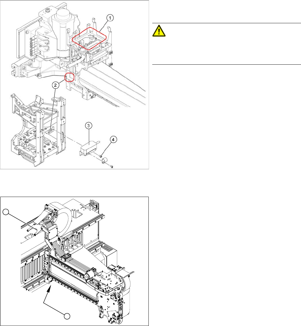
Position of incremental encoder (Y-axis) and the gantry
interface (X-series machine shown as example)
Legend
1. Position of Y-axis incremental encoder (read head)
2. Installation point for gantry interface
► Move the gantry to a suitable position (D1: left side of
machine, D2: center of machine), so that you have
access the incremental encoder easily.
► Unplug the incremental encoder press-fit connection
from the gantry interface (2).
1
2