00195376-05_SM_D1_D1i_D2_D2i_EN.pdf - 第79页
Service Work 4.2.10 X/Y Axis End Position/Reference Proximity Switch Gantries Service Manual SIPLACE D1/D1i/D2/D2i 79 4.2.10 4 . 2 . 1 0 X / Y A x is E n d P o s it io n / R e f e r e n c e P r o x im it y S w it c h X/Y…
Service Work
Gantries 4.2.9 Replacing the Y-Axis Incremental Encoder (Read Head) [03047216S-xx]
78 Service Manual SIPLACE D1/D1i/D2/D2i
Installation
4.2.9
4.2.9 Replacing the Y-Axis Incremental Encoder (Read Head) [03047216S-xx]
Replacing the Y-Axis Incremental Encoder (Read Head) [03047216S-xx]
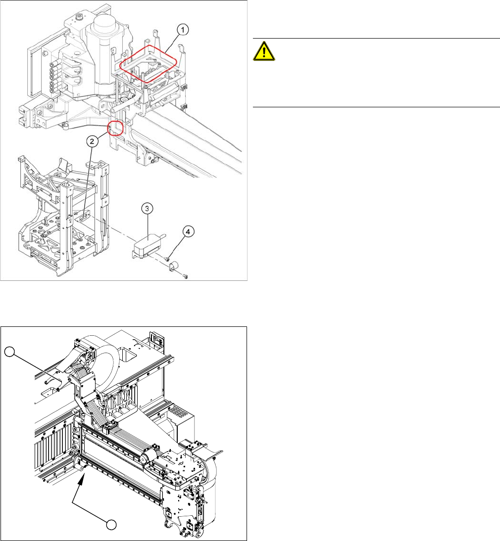
► Tighten the fastening screws (4).
► Reconnect to the electricity supply.
CAUTION! Check how the cables are run!
Make sure that the axes can be moved without damaging
the cables.
Fasten them with cable ties.
► Move the gantry into the end stopper and check that
the bumper does not come into contact with the ca-
ble.
Position of incremental encoder (Y-axis) and the gantry
interface (X-series machine shown as example)
Legend
1. Position of Y-axis incremental encoder (read head)
2. Installation point for gantry interface
► Move the gantry to a suitable position (D1: left side of
machine, D2: center of machine), so that you have
access the incremental encoder easily.
► Unplug the incremental encoder press-fit connection
from the gantry interface (2).
1
2
Service Work
4.2.10 X/Y Axis End Position/Reference Proximity Switch Gantries
Service Manual SIPLACE D1/D1i/D2/D2i 79
4.2.10
4.2.10 X/Y Axis End Position/Reference Proximity Switch
X/Y Axis End Position/Reference Proximity Switch
4.2.11
4.2.11 Replacing the Trailing Cable [03039527-XX]
Replacing the Trailing Cable [03039527-XX]
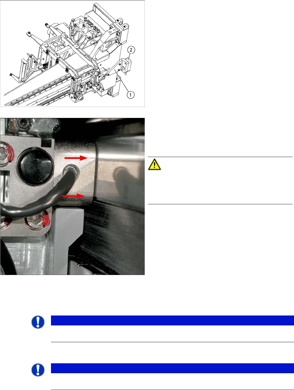
► Unthread the connection cable as far as the incre-
mental encoder.
► Loosen the three screws (1) fastening the incremen-
tal encoder (2) of the Y axis and carefully lift off the
incremental encoder.
► Clean the reading surface of the incremental encoder
(2) with a cloth and ethanol or with a Q-tip.
► Fit the incremental encoder (2) with the three fasten-
ing screws so that there is a gap of 0.4 mm between
the incremental encoder and the scale. Use the cor-
responding thickness gauge (plastic).
Casting marks on the incremental encoder (X-axis on X-
series machine shown as example)
► You must set the exact height to the scale.
► Align the incremental encoder, using the two casting
marks (arrows), which mark the read area.
► Reconnect to the electricity supply.
CAUTION! Make sure that the cables do not rub
against anything.
Make sure that the axes can be moved without damaging
the cables.
Fasten them with cable ties.
NOTICE
End position/reference proximity switches are no longer used on the axes, as their function has
now been taken over by the software of the A364. This function no longer applies.
NOTICE
The trailing cable may only be replaced by specially trained Siemens service technicians. The
procedure is described in a separate manual.
Service Work
Gantries 4.2.12 Replacing the Head Plate Sensors (Temperature Sensor) [03045910-xx]
80 Service Manual SIPLACE D1/D1i/D2/D2i
4.2.12
4.2.12 Replacing the Head Plate Sensors (Temperature Sensor) [03045910-xx]
Replacing the Head Plate Sensors (Temperature Sensor) [03045910-xx]
4.2.13
4.2.13 Replacing the Vision Processor Subboard [03040460-xx]
Replacing the Vision Processor Subboard [03040460-xx]
Overview
Removal
NOTICE
The temperature sensor may only be replaced by specially trained Siemens service techni-
cians. The procedure is described in a separate manual.
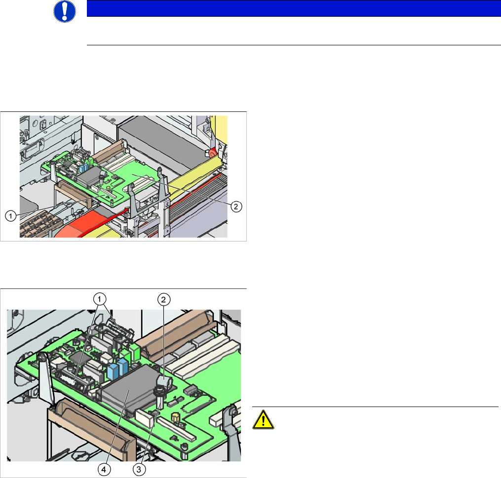
Legend
1. Vision processor subboard (Vision board D series -
total)
2. Gantry head distributor
► Switch off the machine.
► Loosen the cable clamps (1) fixing the flat ribbon ca-
ble to the two cameras and unplug these. Label the
connection points for easier reconnection, later.
► Open the cable clamp (2) for the 4 coax leads of the
SIPLACE Vision system.
► Open the strain relief at the front side of each coax
connector and carefully detach by pulling upwards.
CAUTION! Secure the coax leads, as these are
very easily damaged!
► Unscrew the coax lead support (3) and open the four
screws fastening the board.
► Remove the board. Disconnect the CAN Bus proces-
sor board (4) from the old board and reconnect to the
new one.