00195376-05_SM_D1_D1i_D2_D2i_EN.pdf - 第8页
Contents 8 Service Manual SIPLACE D1/D1i/D2/D2i 6.6.2.1 Set ting the Stat ionary Camera, Types 33, 36 and 25 245 6.6.3 Parameter and Cal ibrations 247 6.6.3.1 Overview of Calibration S teps and Parameters in SITEST 24 7 …
Contents
Service Manual SIPLACE D1/D1i/D2/D2i 7
6.2.3.2 Vision Processor Board (Digital) 210
6.2.3.3 CAN 16 Bit Processor Board (TQ Module) 210
6.2.3.4 Checking the DIP Switches 211
6.3 Track Signals and Zero Pulse 211
6.3.1 Checking the Zero Pulse Signal 211
6.3.1.1 Measuring the Analog Zero Pulse Signal 212
6.3.1.2 Measuring the Digital Zero Pulse Signal 213
6.3.2 Checking the Track Signals 215
6.3.2.1 Analog Track Signals 215
6.3.2.2 Digital Track Signals 217
6.4 Axis Control 218
6.4.1 Axis Control Assemblies 218
6.4.2 Checking the X Axis Dynamics 218
6.4.2.1 Switches and Switch Settings 219
6.4.2.2 Measurement Setup with Adapter Board for A364 219
6.4.2.3 Comparison of X-Axis Travel Profile for C&P6/12 and P&P Heads 220
6.4.2.4 X Axis Travel Time Table, According to Placement Heads 220
6.4.3 Checking the Y Axis Dynamics 221
6.4.3.1 Measurement Setup 221
6.4.3.2 Y-axis Travel Profiles for C&P12 Head 221
6.4.3.3 Y Axis Travel Time Table (D1/D2/D1i/D2i) 221
6.4.4 Overview of Axis Control for Star, Z and DP Axis 222
6.4.4.1 Positioning Time for C&P6 Head 222
6.4.4.2 Positioning Time for C&P12 Head 223
6.4.5 Track Signals for Head Axes 223
6.4.5.1 Overview 223
6.4.5.2 Measurement Setup 223
6.4.5.3 Preparing Track Signals for Star Axis Control (Example) 224
6.4.6 Star Axis Control System 225
6.4.6.1 Checking the Star Axis Dynamics 225
6.4.7 Axis Control of Z Axis 227
6.4.7.1 Checking the Z Axis Dynamics 227
6.4.8 Axis Control of DP Axis 229
6.4.8.1 Checking the DP Axis Dynamics 230
6.5 Collect&Place Head 232
6.5.1 Calibrating the C&P Head and Cameras 232
6.5.2 PCB Boards on the 6/12 C&P Head 233
6.5.3 Overview of Settings on the C&P6/12 233
6.5.4 Setting the Resolution on the Star Axis 234
6.5.5 Setting the Digital Rotary Encoder for the DP Axis 234
6.5.6 Setting the Z axis Belt Tension 235
6.5.7 Adjusting the Stop for the Z Axis 235
6.5.7.1 Tools and Equipment 235
6.5.7.2 General 235
6.5.7.3 Settings 236
6.5.8 Setting the Light Barrier Down 237
6.5.9 Determining the Zero Point Correction for the Star Axis of the C&P Head 238
6.5.10 Adjustment of air pressure values 238
6.5.10.1 Tools and Equipment 238
6.5.10.2 Setting the Air Blast Pressure Values 239
6.5.10.3 Setting the Air Blast Pressure Values with the Compressed Air Testing Device 239
6.5.11 Performing a Vacuum Test on the C&P 6/12 DLM Heads 240
6.5.12 Other Mechanical Settings on the Star 242
6.6 Pick&Place Head 243
6.6.1 Boards at P&P head 243
6.6.1.1 P&P Head Main Board 244
6.6.2 DIP Switch for Camera Types 25, 33 and 36 245
Contents
8 Service Manual SIPLACE D1/D1i/D2/D2i
6.6.2.1 Setting the Stationary Camera, Types 33, 36 and 25 245
6.6.3 Parameter and Calibrations 247
6.6.3.1 Overview of Calibration Steps and Parameters in SITEST 247
6.6.4 P&P Head Parameters 248
6.6.5 Calibrating the D Axis 249
6.6.5.1 Manual Calculation of the D Axis Zero Point Correction 250
6.6.6 Calibrating the Head Height 251
6.6.7 Calibration of Vacuum Distributor on the P&P Head 251
6.6.7.1 Zero Calibration of Vacuum Generator 251
6.6.7.2 Checking the Zero Calibration 252
6.6.7.3 Calibrating the Closed Vacuum 252
6.6.7.4 Checking the Pressure Tightness of the Vacuum System 252
6.6.7.5 Checking the Air Blast 253
6.6.8 Calibrating the P&P Head 253
6.6.9 Mechanical Adjustment of the Z-Axis Incremental Encoder 254
6.6.10 Manual Lowering of Z Axis 254
6.6.11 P&P Head Axis Dynamics 255
6.6.11.1 Z Axis 255
6.6.11.2 D axis 258
6.6.12 Vision DC/DC Converter 259
6.6.13 Transmitting the Head-Specific Data (from SW601) 260
6.7 Modular PCB Conveyor System 261
6.7.1 Setting the Tension of the Conveyor Toothed Belt and the Width Adjustment Unit 261
6.7.1.1 Measuring Points and Belt Tensions for D1/D2 Conveyor 262
6.7.2 Setting the Fixed Conveyor Side (single and dual conveyor) 263
6.7.2.1 Widening the Conveyor (Flexible Dual Conveyor for Single Conveyor Mode) 263
6.7.2.2 Connecting the Dual Conveyor Lifting Tables 264
6.7.2.3 Converting the Single Conveyor Mode Back to Flexible Dual Conveyor Mode 265
6.7.3 Moving the Fixed Conveyor Edge for ’Extra Wide Conveyor’ 265
6.7.4 Checking the Limit Switch Position 266
6.7.4.1 Adjusting the Limit Switch for Initializing the Adjustment Unit 267
6.7.5 Width Adjustment Unit 267
6.7.5.1 Setting the Proximity Switch on the Adjustment Unit 267
6.7.5.2 Setting the Pneumatic Cylinder Proximity Switch on the Adjustment Unit 268
6.7.6 Setting and Checking the Laser Light Barrier for the Stopper Position 269
6.7.7 Function "Constant Transport Time in Placement Area" 270
6.7.8 Light Barrier Functions in Input, Intermediate and Output Conveyors 271
6.7.9 Setting the Clamping Actuator 271
6.7.10 PCB Clamping Check 271
6.7.11 Lifting Table Functions 272
6.7.11.1 Setting the Lifting Table Unit [00358684-xx] 273
6.7.11.2 Adjusting the Lifting Table Speed 273
6.7.12 Jumper Settings for Conveyor Control TSP 201 274
6.7.12.1 Overview 275
6.7.12.2 PCB Handling - Predecessor and Successor Station 275
6.7.12.3 SIEMENS / SMEMA 276
6.7.12.4 Single / Dual Conveyor 276
6.7.13 LEDs on the TSP201 276
6.7.14 Siemens/SMEMA TSP 201 Interface Description 276
6.8 Changeover Table 276
6.8.1 Setting the COT Basic Height 276
6.8.1.1 Tools and equipment 276
6.8.1.2 Adjusting the Component Trolley to the Board Transport Height 277
6.8.1.3 Adjusting the Component Trolley Height 277
6.9 Pneumatic Cutter 278
6.9.1 Jumper setting on the control unit at the tape cutter 278
Introduction
1.1.1 Serial Number of D1/D2 Module Module Description
Service Manual SIPLACE D1/D1i/D2/D2i 9
1
1 Introduction
Introduction
This service guide is a manual or reference work for performing service work on the SIPLACE® D1/D2
placement machines.
1.1
1.1 Module Description
Module Description
1.1.1
1.1.1 Serial Number of D1/D2 Module
Serial Number of D1/D2 Module
1.1.2
1.1.2 Environmentally-Friendly Disposal of Materials and Components
Environmentally-Friendly Disposal of Materials and Components
SIPLACE products are manufactured using only materials and parts that can be easily separated and
disposed of in an environmentally-friendly way. Hazardous materials are not necessary for the installa-
tion, dismantling or operation of the machine.
1.1.3
1.1.3 Use of Original SIPLACE Accessories and Spare Parts
Use of Original SIPLACE Accessories and Spare Parts
Only use original spare parts and authorized accessories. The use of other parts will affect safety and
will invalidate the liability for any consequential damage.
DANGER
Nonobservance of these safety instructions may cause injury to personnel and damage to the
machine!
► Please observe the safety instructions in the operating manual of the according machine
for all service work!
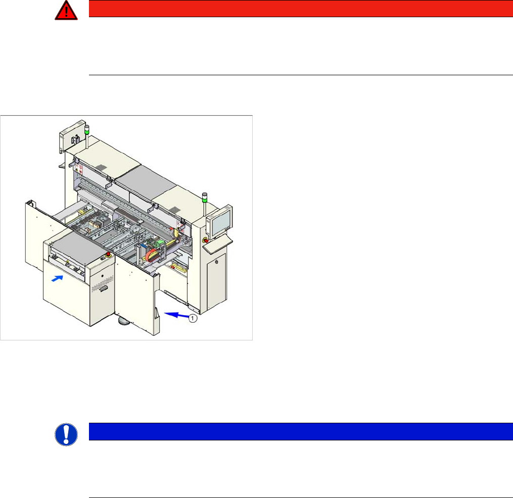
The serial number of your placement machine can be
found on the typeplate (1).
NOTICE
The company operating the system has sole responsibility for the proper, environmentally-
friendly disposal of machines, working materials, consumables and wear parts.
► Please observe your national statutory provisions for waste disposal and environmental
protection.