00195376-05_SM_D1_D1i_D2_D2i_EN.pdf - 第81页
Service Work 4.2.14 Replacing the Gantry Distributo r [03035888-XX] Gantries Service Manual SIPLACE D1/D1i/D2/D2i 81 Installation 4.2.14 4 . 2 . 1 4 R e p la c in g t h e G a n t r y D is t r ib u t o r [ 0 3 0 3 5 8 8 8…
Service Work
Gantries 4.2.12 Replacing the Head Plate Sensors (Temperature Sensor) [03045910-xx]
80 Service Manual SIPLACE D1/D1i/D2/D2i
4.2.12
4.2.12 Replacing the Head Plate Sensors (Temperature Sensor) [03045910-xx]
Replacing the Head Plate Sensors (Temperature Sensor) [03045910-xx]
4.2.13
4.2.13 Replacing the Vision Processor Subboard [03040460-xx]
Replacing the Vision Processor Subboard [03040460-xx]
Overview
Removal
NOTICE
The temperature sensor may only be replaced by specially trained Siemens service techni-
cians. The procedure is described in a separate manual.
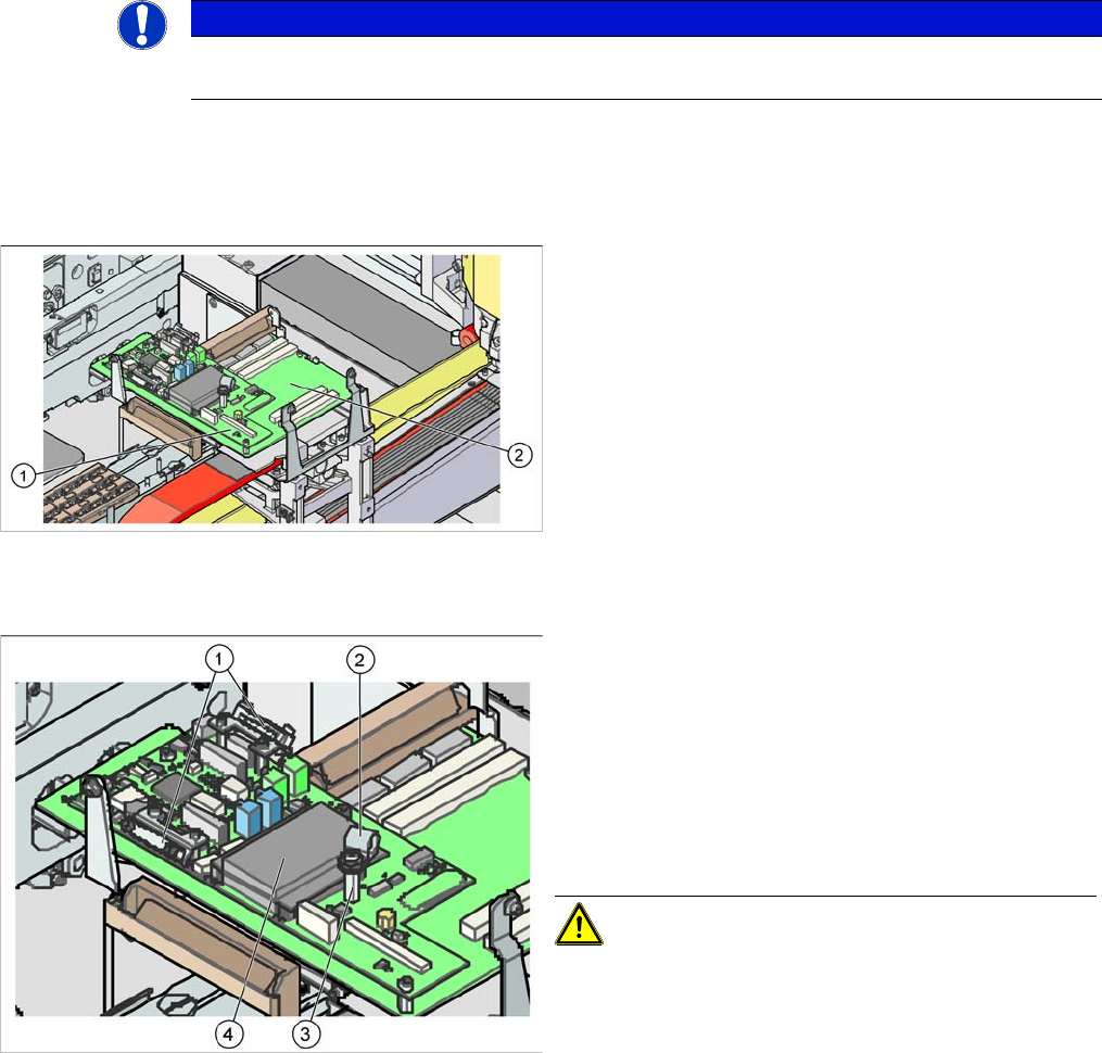
Legend
1. Vision processor subboard (Vision board D series -
total)
2. Gantry head distributor
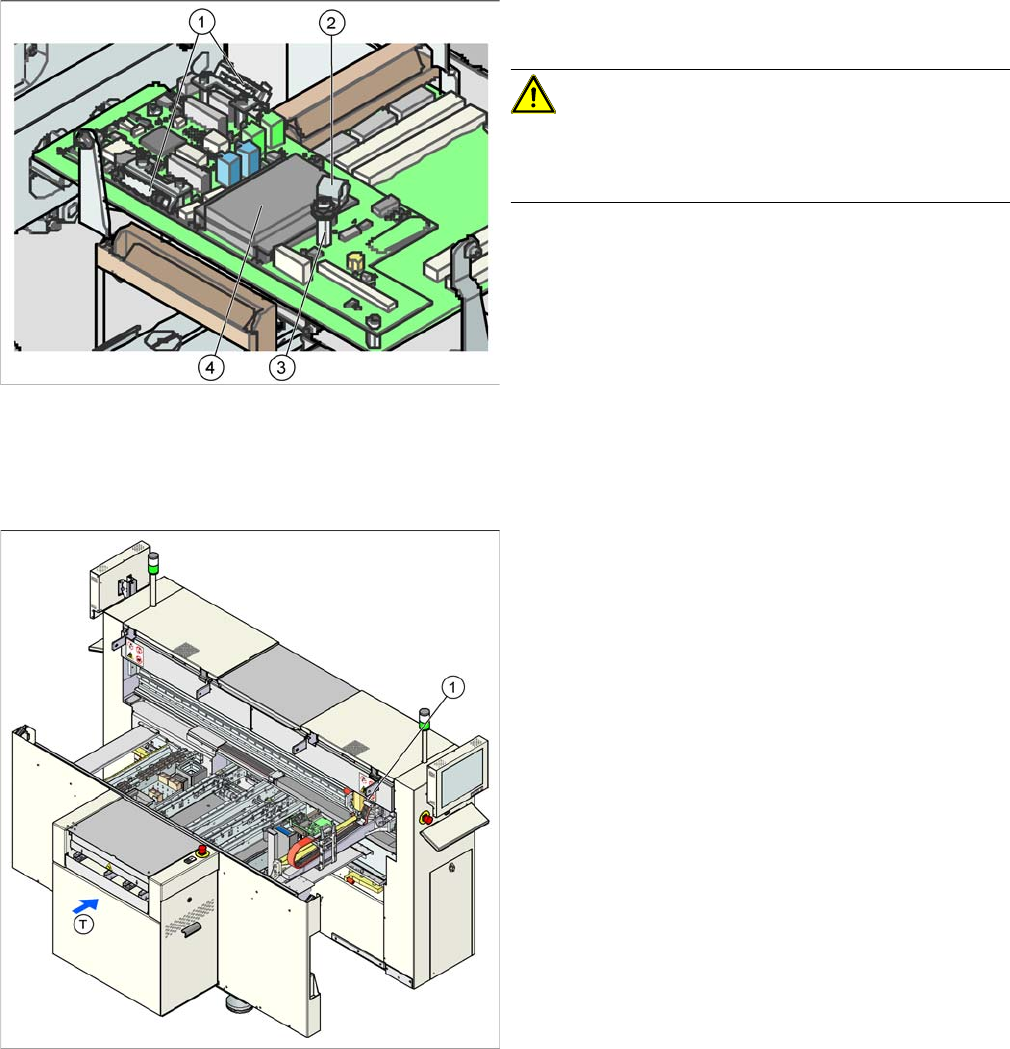
► Switch off the machine.
► Loosen the cable clamps (1) fixing the flat ribbon ca-
ble to the two cameras and unplug these. Label the
connection points for easier reconnection, later.
► Open the cable clamp (2) for the 4 coax leads of the
SIPLACE Vision system.
► Open the strain relief at the front side of each coax
connector and carefully detach by pulling upwards.
CAUTION! Secure the coax leads, as these are
very easily damaged!
► Unscrew the coax lead support (3) and open the four
screws fastening the board.
► Remove the board. Disconnect the CAN Bus proces-
sor board (4) from the old board and reconnect to the
new one.
Service Work
4.2.14 Replacing the Gantry Distributor [03035888-XX] Gantries
Service Manual SIPLACE D1/D1i/D2/D2i 81
Installation
4.2.14
4.2.14 Replacing the Gantry Distributor [03035888-XX]
Replacing the Gantry Distributor [03035888-XX]
Overview
► Installation is performed by following the above in-
structions in reverse order.
CAUTION! Cable clamps for the flat ribbon ca-
ble
Make sure you fit the cable clamps for the flat ribbon ca-
ble, as this provides the ground connection.
► Check the jumper setting for the gantry coding. (See
section.)
Legend
1. Gantry distributor (behind the cover)
Service Work
Gantries 4.2.15 Trailing Cable Interface [03043687-xx]
82 Service Manual SIPLACE D1/D1i/D2/D2i
Removal/Installation
4.2.15
4.2.15 Trailing Cable Interface [03043687-xx]
Trailing Cable Interface [03043687-xx]
Removal/Installation
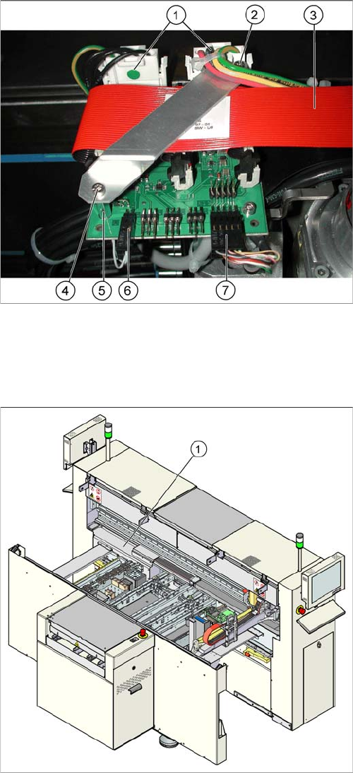
► Switch off the machine.
► Loosen the two screws (4) fastening the flat ribbon
cable holder (2).
► Loosen all electrical connections (1, 3, 6, 7) and label
their positions for easier reconnection, later.
► Detach the two supports for the flat ribbon cable hold-
er (5) and remove the two screws.
► Remove the board and fit the new one by following
the above instructions in reverse order.
Parts
▪ Trailing cable interface [03043687-xx] (D1, D2)
▪ Trailing cable interface [03043686-xx] (D1, D2)
Legend
1. Trailing cable interface for sector 1 (cable host carrier
distributor) (under the cover)
► Remove the cover from the relevant machine side.
► Loosen all electrical connections and label their posi-
tions clearly, for easier reconnection, later.
► Unplug the connections to the Hotlink card, if this
gives you better access. Label the positions for easier
reconnection, later.
► Loosen the eight screws fastening the board and re-
move the board.
► Fit the new board by following the above instructions
in reverse order.