00195376-05_SM_D1_D1i_D2_D2i_EN.pdf - 第9页
Introduction 1.1.1 Serial Number of D1/D2 Module Module Description Service Manual SIPLACE D1/D1i/D2/D2i 9 1 1 I n t r o d u c t io n Introduction This service guide is a manua l or reference wo rk for per forming servic…
Contents
8 Service Manual SIPLACE D1/D1i/D2/D2i
6.6.2.1 Setting the Stationary Camera, Types 33, 36 and 25 245
6.6.3 Parameter and Calibrations 247
6.6.3.1 Overview of Calibration Steps and Parameters in SITEST 247
6.6.4 P&P Head Parameters 248
6.6.5 Calibrating the D Axis 249
6.6.5.1 Manual Calculation of the D Axis Zero Point Correction 250
6.6.6 Calibrating the Head Height 251
6.6.7 Calibration of Vacuum Distributor on the P&P Head 251
6.6.7.1 Zero Calibration of Vacuum Generator 251
6.6.7.2 Checking the Zero Calibration 252
6.6.7.3 Calibrating the Closed Vacuum 252
6.6.7.4 Checking the Pressure Tightness of the Vacuum System 252
6.6.7.5 Checking the Air Blast 253
6.6.8 Calibrating the P&P Head 253
6.6.9 Mechanical Adjustment of the Z-Axis Incremental Encoder 254
6.6.10 Manual Lowering of Z Axis 254
6.6.11 P&P Head Axis Dynamics 255
6.6.11.1 Z Axis 255
6.6.11.2 D axis 258
6.6.12 Vision DC/DC Converter 259
6.6.13 Transmitting the Head-Specific Data (from SW601) 260
6.7 Modular PCB Conveyor System 261
6.7.1 Setting the Tension of the Conveyor Toothed Belt and the Width Adjustment Unit 261
6.7.1.1 Measuring Points and Belt Tensions for D1/D2 Conveyor 262
6.7.2 Setting the Fixed Conveyor Side (single and dual conveyor) 263
6.7.2.1 Widening the Conveyor (Flexible Dual Conveyor for Single Conveyor Mode) 263
6.7.2.2 Connecting the Dual Conveyor Lifting Tables 264
6.7.2.3 Converting the Single Conveyor Mode Back to Flexible Dual Conveyor Mode 265
6.7.3 Moving the Fixed Conveyor Edge for ’Extra Wide Conveyor’ 265
6.7.4 Checking the Limit Switch Position 266
6.7.4.1 Adjusting the Limit Switch for Initializing the Adjustment Unit 267
6.7.5 Width Adjustment Unit 267
6.7.5.1 Setting the Proximity Switch on the Adjustment Unit 267
6.7.5.2 Setting the Pneumatic Cylinder Proximity Switch on the Adjustment Unit 268
6.7.6 Setting and Checking the Laser Light Barrier for the Stopper Position 269
6.7.7 Function "Constant Transport Time in Placement Area" 270
6.7.8 Light Barrier Functions in Input, Intermediate and Output Conveyors 271
6.7.9 Setting the Clamping Actuator 271
6.7.10 PCB Clamping Check 271
6.7.11 Lifting Table Functions 272
6.7.11.1 Setting the Lifting Table Unit [00358684-xx] 273
6.7.11.2 Adjusting the Lifting Table Speed 273
6.7.12 Jumper Settings for Conveyor Control TSP 201 274
6.7.12.1 Overview 275
6.7.12.2 PCB Handling - Predecessor and Successor Station 275
6.7.12.3 SIEMENS / SMEMA 276
6.7.12.4 Single / Dual Conveyor 276
6.7.13 LEDs on the TSP201 276
6.7.14 Siemens/SMEMA TSP 201 Interface Description 276
6.8 Changeover Table 276
6.8.1 Setting the COT Basic Height 276
6.8.1.1 Tools and equipment 276
6.8.1.2 Adjusting the Component Trolley to the Board Transport Height 277
6.8.1.3 Adjusting the Component Trolley Height 277
6.9 Pneumatic Cutter 278
6.9.1 Jumper setting on the control unit at the tape cutter 278
Introduction
1.1.1 Serial Number of D1/D2 Module Module Description
Service Manual SIPLACE D1/D1i/D2/D2i 9
1
1 Introduction
Introduction
This service guide is a manual or reference work for performing service work on the SIPLACE® D1/D2
placement machines.
1.1
1.1 Module Description
Module Description
1.1.1
1.1.1 Serial Number of D1/D2 Module
Serial Number of D1/D2 Module
1.1.2
1.1.2 Environmentally-Friendly Disposal of Materials and Components
Environmentally-Friendly Disposal of Materials and Components
SIPLACE products are manufactured using only materials and parts that can be easily separated and
disposed of in an environmentally-friendly way. Hazardous materials are not necessary for the installa-
tion, dismantling or operation of the machine.
1.1.3
1.1.3 Use of Original SIPLACE Accessories and Spare Parts
Use of Original SIPLACE Accessories and Spare Parts
Only use original spare parts and authorized accessories. The use of other parts will affect safety and
will invalidate the liability for any consequential damage.
DANGER
Nonobservance of these safety instructions may cause injury to personnel and damage to the
machine!
► Please observe the safety instructions in the operating manual of the according machine
for all service work!
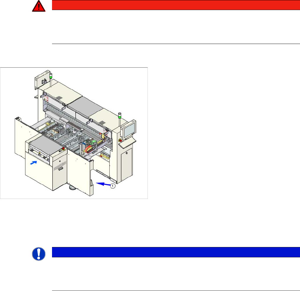
The serial number of your placement machine can be
found on the typeplate (1).
NOTICE
The company operating the system has sole responsibility for the proper, environmentally-
friendly disposal of machines, working materials, consumables and wear parts.
► Please observe your national statutory provisions for waste disposal and environmental
protection.

Introduction
Key Information 1.2.1 Information About This Service Manual (Customer Version)
10 Service Manual SIPLACE D1/D1i/D2/D2i
1.2
1.2 Key Information
Key Information
1.2.1
1.2.1 Information About This Service Manual (Customer Version)
Information About This Service Manual (Customer Version)
The service work described in this manual may only be performed by specially trained service techni-
cians, with appropriate qualifications and expertise.
If you should have any questions during the service work, please contact the SIPLACE customer hotline
directly:
(0049) 089 20800 48642
or send an e-mail to: hotline.siplace@siemens.com.
1.2.2
1.2.2 Validity of Document
Validity of Document
This document contains instructions about the service work for all D1 and D2 machines from the
SIPLACE D series.
The service work is listed on a module by module basis:
▪ If the work required for specific machines should differ from the standard procedure, this will be in-
dicated with reference to the machine number, series and various delivery statuses.
▪ Diagrams should be seen as examples e.g. the diagram of a SIPLACE D1 or machine with different
paint finish does not mean that the following information only applies to the machine type shown.
The main focus of this manual is on a description of mechanical service work.
Please refer to the circuit diagram folder supplied with your machine for any electrical checks:
▪ Siplace D1/D2 circuit diagram folder, item no. 00194841-xx (German and English)
1.2.3
1.2.3 Release History
Release History
1.2.4
1.2.4 SIPLACE on the World Wide Web (WWW)
SIPLACE on the World Wide Web (WWW)
Log into our SIPLACE® homepage at http://www.siplace.com.
► Select either the German or English version.
The different sections contain information about our products, services and contact persons.
In addition, registered customers can access the
SIPLACE User Group
. Here you can call up special
information about our placement systems e.g.
▪ Technical documentation,
▪ Technical information,
▪ Spare parts lists etc.
Registration for the user group is very simple:
► Click on the Register link.
► Fill in the registration form and send it off to us.
Soon afterwards, you will receive your access authorization with USER ID and password.
Release Changes
12/2006 First edition
05/2007 Corrected version
The following sections have been omitted, as these service tasks may only be per-
formed by the SIPLACE service engineers:
Replacement and dismantling of magnetic strips, replacement of the Y motor, re-
placement of the X and Y scales
08/2008 Corrected version
Revision of the C&P and Twin Head chapters
11/2013 Corrected version
Revision of the PCB conveyor system chapter