00195376-05_SM_D1_D1i_D2_D2i_EN.pdf - 第96页
Service Work PCB conveyor system 4.3.5 Replacing the Lifting Table Unit [00358653] 96 Service Manual SIPLACE D1/D1i/D2/D2i Removal Installation Replacing the lifting table unit (example of dual conveyor shown) ► Move the…
Service Work
4.3.5 Replacing the Lifting Table Unit [00358653] PCB conveyor system
Service Manual SIPLACE D1/D1i/D2/D2i 95
Installation
4.3.5
4.3.5 Replacing the Lifting Table Unit [00358653]
Replacing the Lifting Table Unit [00358653]
Parts
▪ Lifting table unit for single conveyors [00358653-xx]
▪ Lifting table unit for dual conveyors [00358654-xx]
Overview
CAUTION!
Do not damage the toothed belt!
The toothed belts must not be stretched or kinked!
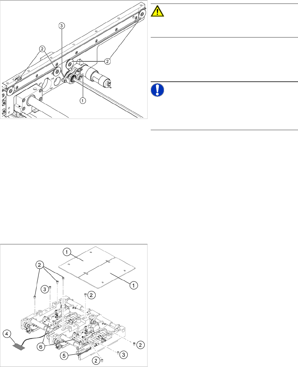
► Feed the new conveyor toothed belt (3) into the drive
unit and weave it round the deflection pulleys (2).
► Insert the tape drive (mount) or drive unit (1) with the
conveyor toothed belt (2) and fasten.
NOTICE!
When replacing the belt on the passive side (tape drive
without drive unit), set the track width to 50 mm. The
tape drive must be aligned towards the active side, allow-
ing smooth axial movement of the hexagonal shafts.
► Tighten the fastening screws.
► Adjust the belt tension. (See "6.7.1 Setting the Ten-
sion of the Conveyor Toothed Belt and the Width Ad-
justment Unit" [ ➙ 261].)
Replacing the lifting table unit (example of dual conveyor
shown)
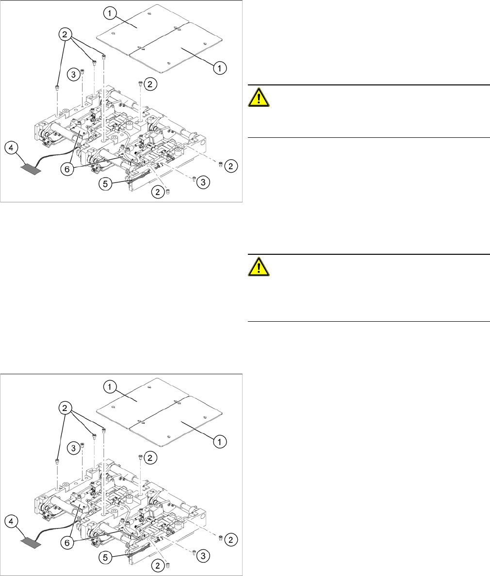
Legend
1. Lifting table plates
2. 6 x fastening screws for lifting table (M8 x 100) (4 x
for single conveyors)
3. 2 x fastening screws for the lifting table (M8 x 50)
Service Work
PCB conveyor system 4.3.5 Replacing the Lifting Table Unit [00358653]
96 Service Manual SIPLACE D1/D1i/D2/D2i
Removal
Installation
Replacing the lifting table unit (example of dual conveyor
shown)
► Move the PCB conveyor to a suitable position (e.g.
maximum width), from which you have best access to
the lifting table unit.
► Loosen the screw fastening the lifting table plate (1)
and remove the lifting table plate from the lifting table
unit.
CAUTION!
Never use a ball-head Allen wrench to loosen the screws
fastening the lifting table plates.
► Loosen the screws (2) and (3), fastening the lifting ta-
ble unit.
► Remove the cover on the conveyor conversion board
(6) and unplug the connection cable (4) from the lift-
ing table unit.
► Unplug the compressed air connection (5).
► Carefully lift the lifting table off the locating pins.
CAUTION!
Heavy machine part!
When removing the lifting table, remember it is heavy
(17.5 kg).
Replacing the lifting table unit 2 (example of dual convey
-
or shown)
► Lift the lifting table unit into the machine and position
it on the locating pins.
► Screw in the fastening screws (2) and (3).
► Reconnect to the electrical (4) and compressed air
(5) systems.
► Check the lifting table speed and the functionality of
the PCB clamping device, without the lifting table
plate.
► Set the values according to the table in "6.7.11.2 Ad-
justing the Lifting Table Speed" [ ➙ 273].
► Carefully place the lifting table plates (1) onto the lift-
ing table unit and tighten the fastening screws diago-
nally, so that the lifting table plate does not stick.
► Check the lifting table speed once the lifting table
plate has been installed. (See "6.7.11.2 Adjusting the
Lifting Table Speed" [ ➙ 273].)
Service Work
4.3.6 Replacing the Lifting Table Stabilizer (Stabilizer Unit) [00358684-xx] PCB conveyor system
Service Manual SIPLACE D1/D1i/D2/D2i 97
4.3.6
4.3.6 Replacing the Lifting Table Stabilizer (Stabilizer Unit) [00358684-xx]
Replacing the Lifting Table Stabilizer (Stabilizer Unit) [00358684-xx]
Overview
Tools and equipment required
▪ Torque wrench with plug-in ratchet [00386175-xx]
▪ Plug-in wrench 16 mm [00386177-xx]
Removal
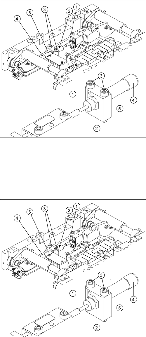
1. Actuator
2. Locknut
3. Fastening screws
4. Handle
5. Stabilizer [00358684-xx]
The stabilizer enables the lifting table to be moved gently
upwards. It prevents the PCBs from being clamped in
with too much impact.
The stabilizer consists of the shock absorber [00367737-
xx] and the damping block [00367782-xx].
► Move the PCB conveyor to the position which gives
you best access to the lifting table.
► Move the Y gantries into the area outside the PCB
conveyor.
► Switch off the machine and secure it to prevent unau-
thorized reactivation.
► Loosen the screws fastening the lifting table plate and
remove the lifting table plate from the lifting table unit.
► Loosen the two screws (3) holding the stabilizer (5).
► Undo the locknut (2) and take the stabilizer by its han-
dle (4), twisting it out of the mounting block.